I am in the process of building a new 3R layout that will start out with two 40’ loops and one siding on an L shaped configuration. My question while under construction, how many power connections should I plan for each loop? I will be using a Z-4000 power supply. A new to me coming from G scale. Thanks.
Replies sorted oldest to newest
I connect about every 6 feet. I only run conventional. JohnA
Thanks John. Closer than I thought.
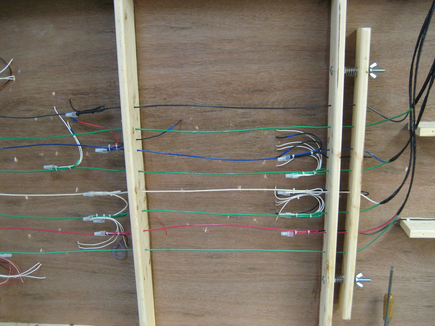
Rich I am on my third layout. It's 2-rail but I have found that no matter what in the end I have power feeds to every section of track. The joiners just don't do the job over time and vibration.
Chuck
@Rail Dawg posted:Rich I am on my third layout. It's 2-rail but I have found that no matter what in the end I have power feeds to every section of track. The joiners just don't do the job over time and vibration.
Chuck
Just to clarify: you have a feed to every section? Even if it's just 5" or 10"? I've never seen anyone recommend that. Are there any downsides to that many feeds (besides cost)?
I'm about to wire a new 3R layout that is a lot bigger and more complex than any I have done before and i'm looking for tips. Thanks.
@Rail Dawg posted:Rich I am on my third layout. It's 2-rail but I have found that no matter what in the end I have power feeds to every section of track. The joiners just don't do the job over time and vibration.
Chuck
What happened to the silver epoxy that was going to free you from all those power drops? ![]()
Another guideline is based on the number of track joints between power connections. I cannot remember the accepted number, however I believe it may be about 10 joints between drops. (each drop goes 5 joints in each direction, thus 2x5=10 joints between connections.
Someone please supply the more accurate value. Its been many years since I wired my layout, so 10 is a guesstimate.
Every 12 sections of track regardless of length of track! 12 -1.5" sections or 12 -30" sections, doesn't matter. Every 12 sections. It was suggested years ago when I started by this forum and mainly Barry who wrote the book on MTH DCS. Whether DCS or Legacy I use 12 section rule. And yes you can go longer but that is what was recommended!
NOTE! Track makes a difference. Atlas rail joiners will work loose after few years. No problem as I just solder the joiner when it works loose but you have been warned!
Curtis
The folks at Lionel recommend at least 16 gauge wire (14 or 12 gauge wire is better) and feeder wires attached to the track every 4-6 feet. Are you planning to use command-control? If so, Legacy/TMCC requires bus wiring, while MTH DCS requires star wiring.
@gunrunnerjohn posted:What happened to the silver epoxy that was going to free you from all those power drops?
I am going with the silver epoxy at every joint in my new layout and am not going to place a hundred plus power feeds.
Because it is experimental I'm not ready to tell others to do the same. But my testing has made it quite clear that the silver epoxy is superior to soldering a bunch of wires to the rails. After decades of being around the railroads I have yet to see one instance of them welding power feeds directly to the rails. ![]()
Of course I'm going to catch grief because I am bucking the norm.
Chuck
Thank you for all the suggestions. I’m using new Atlas track and since I’m using long lengths, I think I’ll try the 6-8’ spacing. 12 gauge stranded garden wire is a good choice as it is flexible and easy, but may be excessive for the lengths planned. However, since I have a considerable quantity of 12 gauge wire that I also use on my G layout I’ll give it a try. A lot of good advice.
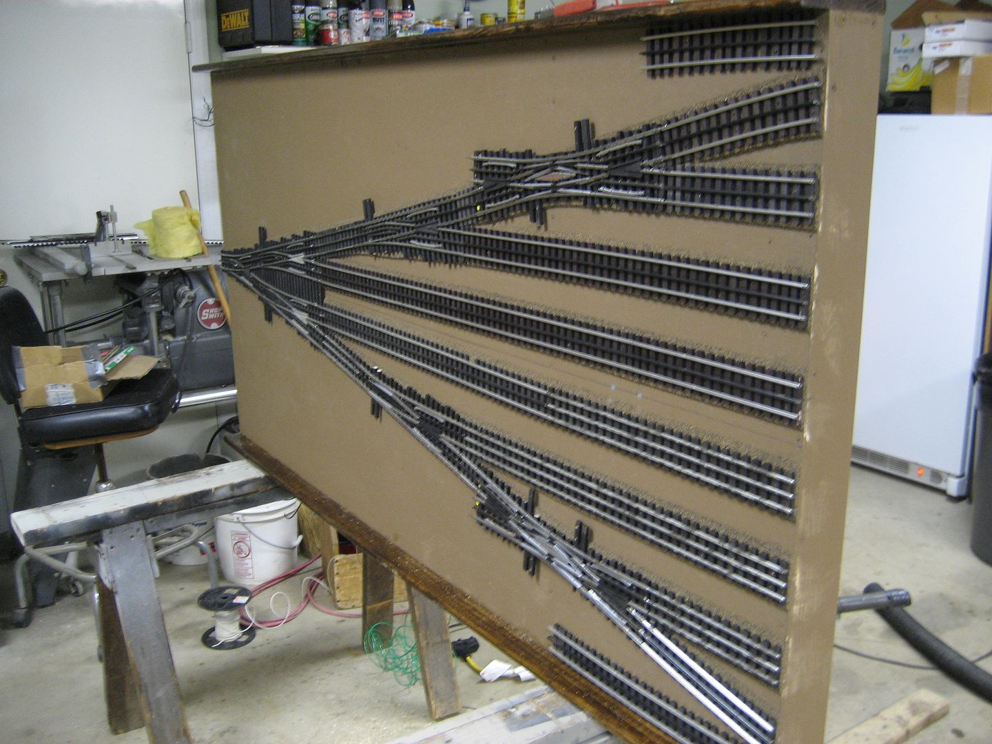
Fort Pitt modular layout, eventually, every track joint was soldered. Gargraves track, Ross/or Gargraves switches. Each 6ft (length) module had at least one wire feed. Yard throat module, (pictured), with a Curtis Ross 4 way yard throat (turnout) switch.


For those using Ross switches, and Gargraves track, note that the pins (track joiners) are a slightly different size. IMO, enough difference, to degrade the electrical connection, at the track joint, (Eventually).


