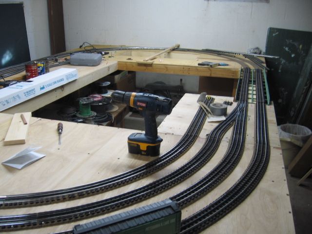
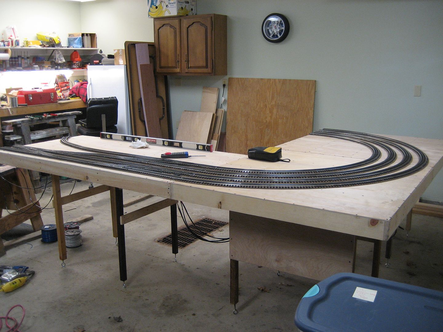
What methods does everyone use when putting down your radius on your bench work?  I have been extending out a board and using a string like a compass to draw the radius.  I use the drawn line to line up my roadbed when gluing it down.

Are there better and/or easier methods?

Original Post

Replies sorted oldest to newest

Your method of using a string (trammel) will work just fine to make a nice, even curve with the radius of your choice.  However, the goal of some model railroaders is to have 'eased' curves (like the prototype), which involves a constantly shortening radius from the beginning of the curve to the center, then the reverse back to the straight. 

This way the loco and the train will 'ease' into the curve a little at a time, instead of going immediately from straight to full radius.  Sound complicated?  It IS, if you lay it out with varying lengths of string (changing radius every six inches or so).  However, there's a MUCH easier way to lay out curves WITH easements, which look really great, and avoids having the consist jerk into the curves.  Here's how to do it:

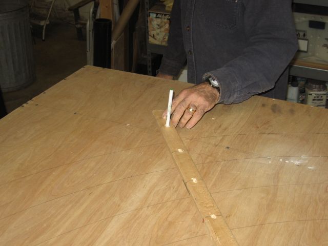
Use a special stick, the FULL length of the curve, plus a coupla feet or more.  The stick should be about 1/8" thick (less if you can), and an inch or so in width. 

Determine the two points on your benchwork where the curve starts, and where it stops.  Drive a pair of finish nails at those points, just enough apart to accommodate your stick's thickness, and another pair of nails about a foot further down the trackline on the straight portion.  Do this at both ends of the curve.

Now insert the stick (on edge) between all the nails, and the shape of an eased curve will magically present itself as the stick has to bend to make the curve but, since it's being held straight at both ends will cause it to automatically create the desired easement into the curve. 

It's a LOT easier done than written and, in the time it took to write all this down, one could have 'easily' laid out an eased curve, which would be appreciated by not only your trains, but also the viewers eyes.

I hope all that makes sense.  If it's confusing, let me know, and I'll do my best to describe it from another vantage point.  Once you've done it, you'll slap your forehead and say "Dang...that was really simple, and works (and looks) GREAT!"  Or something to that effect...


Hoping that helps more than confuses,

Mark in Modesto

You will also need to allow an "offset" between the centerline of the straight track and the center line of the fixed-radius curve, otherwise there will be no "easement" between the two points. For example, you can plot the centerline of the fixed-radius curve so that it lies a certain distance inside the centerline of the straight track that it is designed to meet. The distance separating these centerlines is  the "offset." In other words, don't plot the curve so that it's centerline matches up exactly with the straight track, but set it in a certain distance (the "offset").

Then measure back an equal distance on both the fixed curve and the straight track from the point at which the curve and straight would have intersected if there had not been an offset in order to establish the end points of the "easement.' Various authors (e.g. Paul Mallory in his book on track work) suggest using an "easement" whose total length is greater the length of the longest piece of equipment that will pass through the curve. On my own 2-rail layout with very broad curves, I used an offset of about 3/4" with a total easement length of about 24". 

Using a flexible stick that is longer than the full length of the "easement," secure a couple of feet at one end along the centerline of the fixed curve and a couple of feet at the other end along the centerline of the straight track (drive nails on each side of the stick to make it conform to the centerline). The flexible stick will then assume a natural curve of increasing radius between the two points, and you can trace the resulting centerline, which will give a visual approximation of a spiral easement.

It's worth the trouble, because it makes the trains flow nicely into and out of a fixed-radius curve.

I think the folks above have explained things very well. Here is a link to some pictures that might go along with their nice well written descriptions. Not sure about the easement parts though. This is one of my favorite build threads and it helped me a lot with my Atlas track. Lots of good tips and the whole thread is well worth reading, IMO. If you scroll up from the linked post there are some track centering gauges (to keep things properly centered) that Alex built which I also copied and they worked very well. 

Forum member Ingeniero No1's build thread track curves

TexasSP (Brian?), I have a coupla few questions, if I may:

Will your benchtop be a solid sheet on top, or precut sub-roadbed?

What do you plan to use for the actual roadbed?

Do you have either a table saw, or circular saw (aka Skilsaw)?

You're getting pulled in multiple directions, and I'd like to assist, but the answer to those questions will probably help us all advise you best. 


Mark

Mark, yes, Brian it is.

Bench top 3/4 birch, flat top

Road bed, woodland scenics foam

Have circular, miter and jigsaw 

No sub road bed

Right now two loops around a 14.5 x 12.5 room, shelf style.  However, 3 sides are 24 inches deep, the fourth is 16 inches. There is a duck under section which will have a removable bridge section.  Shelf system from container store. Bracing where required.  Shelves above layout for train storage and display 

Thanks, Brian.  If I were doing what you're doing, I would definitely use the long stick on edge to mark the centerlines.  It's super easy, and you get the easements automatically, and for free.

It sounds like you have a nice space for your layout...wide curves possible, not too large to maintain, and runaround capability.  Sweet.  Sometimes it's fun to just set one going around, and sit there watching the thing with your favorite refreshment(s) close at hand.

Birch ply?  Nice...


All the best,

Mark

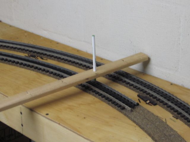
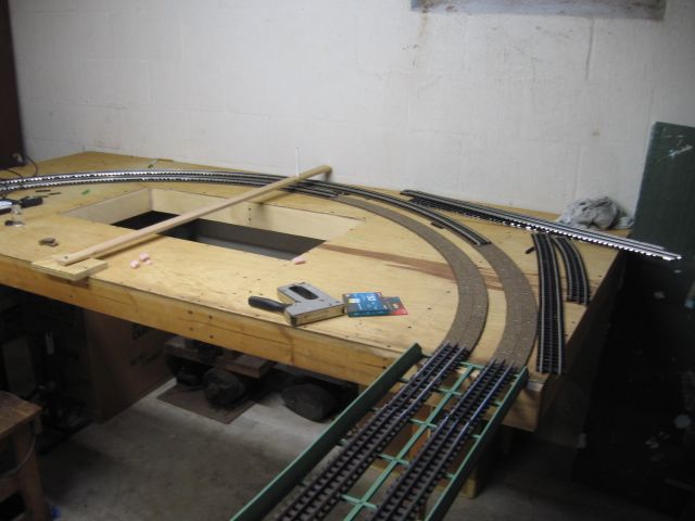
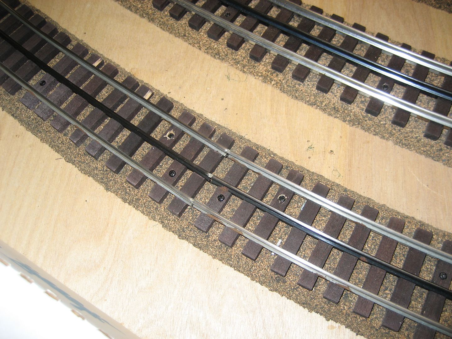
Made a large compass.  The Gargraves  flex track is screwed in place using the compass/ball point pen as a center gauge. Atlas track screws were applied about every 4" around the curves, to hold the track in place.  Track ends were squared/ long inside tracks cut, at the end of each track section, before installing the next piece.  ties were adjusted and positioned as the screws were installed.   All track and switches pictured, were used/re-cycled.  Midwest Cork road bed. Key was ball point pen on the center rail all the time. The drill bit, used to drill holes for the ball point pen, was a lucky/snug fit.  

Best wishes with your project.  Mike CT.

Last edited by Mike CT

Seems like I could have cheated my way through a few Frenched tangents back in the days of architectural drawing by hand just using that stick trick.  Oh man, the math to be saved alone..lol. 

I sort of speed readed my way through so might have missed it, but wood hardness or thickness could vary the easement rate even further .

For users of Gargraves sectional curved track, keep in mind the centerline is NOT dimensionally the same as the size they call it:

http://www.gargraves.com/diagramsandinstructions.html

Look under "Curved Track Specs".

072 curves are 72.59" center rail to center rail (with plastic ties) and 73.42 (with wood ties), that's 19/32" to 1-7/16" difference.  Not sure about other brands such as Ross or Atlas.

The exact hardness of thickness of the strip of wood used to draw the easement doesn't make much practical difference; the strip only needs to be flexible enough to work with and not so flimsy that it becomes distorted when you run a pencil or pen along the edge in order to draw the centerline. In my experience, the most important thing is to have a sufficient length of the strip secured along the fixed-radius curve at one end and along the tangent track at the other end (18" - 24"). Without sufficient overlap, the strip will not form smooth transitions to the curve and the tangent. 

Bob Delbridge posted:

For users of Gargraves sectional curved track, keep in mind the centerline is NOT dimensionally the same as the size they call it:

http://www.gargraves.com/diagramsandinstructions.html

Look under "Curved Track Specs".

072 curves are 72.59" center rail to center rail (with plastic ties) and 73.42 (with wood ties), that's 19/32" to 1-7/16" difference.  Not sure about other brands such as Ross or Atlas.

Believe that difference is due to their wanting to have a tie on each. So the Wood circle is a little over 13/16" larger in diameter? Bet with 3 foot straights between the two different half circles no one or ant train would even notice the difference.


RTR provided the link, above, to my thread where I described how I drew the arcs to place the Atlas track, and the method worked perfectly. Except for three or four lengths of flex track, I used all sectional curved track, but even though the sections are exactly the diameters indicated, they can easily be misplaced if a center guide line is not used.

With the compass drawn lines, and cutting the curves and straights precisely per RR-Track diagrams when required, the actual track layout ends up the same as the RR-Track designed layout.

I used metal rulers (48" and 72") to make the compasses. Using rulers makes it easy to drill holes for the pivot and the pencil at the desired spots for the various radii. My mains are Ø108" and Ø99", and I have a few  Ø90" and Ø81" at the yards and spurs. One thing to remember: Depending on where the curve is located, the extra length of the 'compass' may need to extend past the pivot location, or past the scribing (pencil) end. A partially sharpened screw makes an easily relocatable pivot.

Good luck,

Alex

Go to your local paint or hardware store and obtain 2  36" yardsticks. They are often given away free. Screw them together with about 6' of overlap. Then, drill holes every inch or two at the desired radii. Drill a pivot hole at the base of where the two yardsticks overlap. Thus, you have a large compass for little or no cost. After you draw your radii with a number 2 pencil, lay Midwest cork roadbed along the radius line. This is simple because the Midwest cork roadbed is split down the middle. Then align the Gargraves track with the roadbed. Pre-drill the ties and secure the track with 3/4 inch number 4 wood screws. Trim the track ends with a Dremel and a large fiberglass cut off wheel or a zone saw. Be sure to wear safety glasses when you use the cut off wheel. Use Ross Custom switches for your turnouts powered by Tortoise switch machines and you have the best track system going. Ballast as you desire or not. You can bend the Gargraves track around your abdomen or the water heater. Just be sure to re-align the ties after each bend to avoid kinking. Enjoy, track work is some of the best stuff you will do on your layout.

BobbyD posted:

Believe that difference is due to their wanting to have a tie on each. So the Wood circle is a little over 13/16" larger in diameter? Bet with 3 foot straights between the two different half circles no one or ant train would even notice the difference.


The only issue I see is if a person draws a 36" radius on his layout, draws straight lines to connect the radius, then lays track they're going to be in for a surprise when one end of the curve doesn't line up with the drawn lines.

I don't still see why the Gargraves track with wood ties has a different center-to-center diameter than their track with plastic ties. But, as long as you draw a centerline with a radius that corresponds to what's given in the Gargraves specs for the type you are using, then there won't be a problem lining up with the straight sections.

Add Reply

Post
The Track Planning and Layout Design Forum is sponsored by

AN OGR FORUM CHARTER SPONSOR
×
×
×
×
Link copied to your clipboard.
×
×