Ed
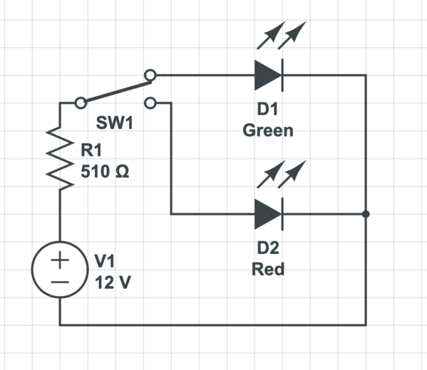
From your last post you mentioned that you were using 3VDC Hankscraft stall switch motors. Here is a circuit from a similar stall motor from Switchmaster:

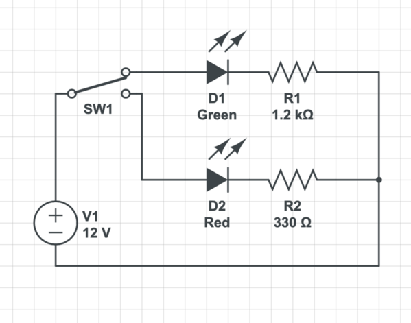
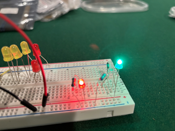
So the LEDs could be wired between the last DPDT switch and the Hankscraft motor (ignore the 2 diodes and 2 incandescent lamps on the right). This eliminates the need for the separate cherry switch. Depending on the polarity of the power to the motor, one or the other LED lights since they are wired opposite of each other. If they are reversed (eg. green when you want red), reverse both LEDs.
Assuming your supply voltage is 3VDC, for the green LED I would use a 22 Ohm resistor, and for the red LED I would use a 47 Ohm resistor.
LED basics
1. LEDs are polarity sensitive devices. They only light up when the current flows in the one correct direction.
2. Here is how to identify the anode (+) and cathode (-) leads
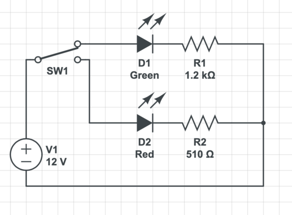
3. LED must have their current limited. This is commonly done with a current limiting resistor in series with the LED. The resistor value is calculated based on the supply voltage, the forward voltage of the LED (usually 2V for red, and 2.6V for green LEDs), and the intended current to be supplies (usually 20ma). You can use this online LED calculator, or use the "50 rule" which says the resistor value is 50 x (supply voltage - LED forward voltage).
Red LED: 50 x (3V - 2V) = 50 Ohms
Green LED: 50 x (3V -2.6V) = 20 Ohms
You can move up or down a little to match common resistor sizes which is what I did. The LED Calculator also tells you the minimum resistor wattage which in your case is only 1/8 watt, and you can use the commonly available 1/4 or 1/2 watt resistors. Note that will higher supply voltages 12V, 18V etc, you will need a larger value resistor.
If you still want to use a cherry switch, let me know and I will diagram it for you.
Bob


