Hey Gang,


I'm editing the post to make this tutorial a little more user friendly. This tutorial will assist in wiring the Atlas 6924 non-derail board with the Atlas #57 switch control. It will not cover powering the closure rails. I'll be breaking down the wiring into two parts covering power and common, and isolated rail detection and switch machine control. I'll also include a testing and troubleshooting section at the end should you encounter any problems as I did.


The wiring will follow Atlas' schematic with the following exceptions: the color of the wires will be different and all power will come from the accessory side of the transformer.


Materials Used

  • Atlas 6924 Non-Derail Board
  • Atlas #57 Switch Control Box
  • Atlas #312 5 Conductor Ribbon Wire
  • Barrier Strips

The 5 conductor ribbon wire is optional, but I found very useful. It provided 5 different colors which made keeping track of each wires function easier and helped reduce any confusion during wiring. The barrier strips are also optional. This was a personal decision of mine as I found it easier to assist in troubleshooting rather than splicing wires together and then having to undo the splice.


Wire Reference

  • Power - Red (exception: red wire running from the switch motor to 6924)
  • Common - Black
  • Isolated Rail Detection and Direction Control -Blue and Yellow
  • Switch Motor - Red and Green
  • Switch Motor Common - Black 

The color scheme was changed to fall in line with my layout wiring in which red is used for power and black is used for common. It made more sense to me that if I were holding a red wire, it was meant to power something. If you already have a layout built and used different color wiring, simply substitute your wiring color scheme.


Wiring Power and Common


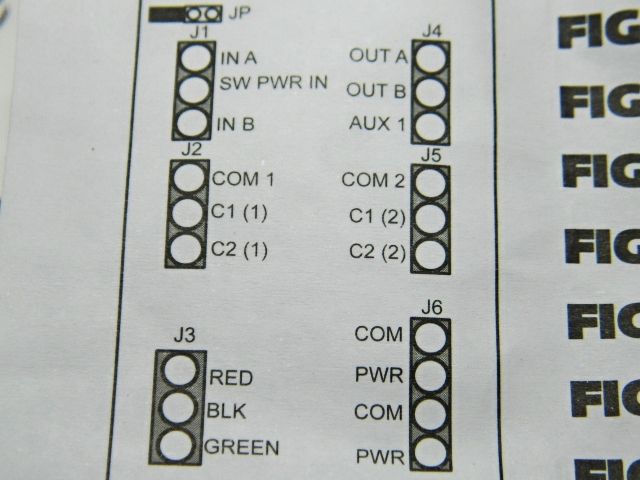
In order to operate, the 6924 n/d board requires a power supply of 6v - 22v AC/DC supplied to J6. I chose the accessory side of my transformer for all power inputs into the 6924 to eliminate the need for a second power source.


Power (red) is routed to the following terminals:

  • 6924 terminal J1 - SW PWR IN
  • 6924 terminal J5 - COM 2
  • 6924 terminal J6 - PWR

Common (black) is routed to the following terminals:

  • 6924 terminal J6 - COM
  • #57 Switch Control terminal labeled C - Take special note and care when wiring to the #57. Connecting to the posts with the red X will damage the 6924 n/d board.
  • Switch Machine terminal labeled BL

This tutorial only covers the use of one 6924. The 6924 can be daisy chained to supply power to additional 6924's. To enable this function, install the jumper on JP 1. refer to the Atlas instructions for further wiring. 


pwrcomwiring


Isolated Rail Detection and Switch Machine Control


Through Route Detection (Yellow)


The through route isolated rail detection wire and the wire from the #57 switch control terminal labeled 1 will be connected. (In my case, I used a barrier strip.) The connected wires are then run to the 6924 terminal J1 IN A. Next, connect the #57 switch control terminal labeled 3 to the 6924 terminal J5 C1-2.


Diverging Route Detection (Blue)


The diverging route isolated rail detection wire and the wire from the #57 switch control terminal labeled 2 will be connected. The connected wires are run to terminal J1 IN B. Next, connect the #57 terminal labeled 4 to the 6924 terminal J5 C2-2.


Switch Machine Control (Red, Green)


Connect the wire from the switch machine terminal labeled G to the 6924 terminal J4 OUT A. Connect the wire from the switch machine terminal labeled R to the 6924 terminal J4 OUT B.


detectionandcontrol


Testing and Troubleshooting


Before turning on the power supply, ensure the power is set to within the 6v - 24v range. (Since I am using TMCC, my power preference is 18v to keep things logical and in order for my taste. The transformers I will be using allow me to set a custom voltage. Other transformers may have a set output. Just ensure it is within range.)


Turn on the transformer and look for the LED located on the 6924. If it is lit, the 6924 is receiving power. If it is unlit, check for proper voltage and any loose connections.


Set the #57 Switch Control for the through route*. Move the lever to N** and press the activation button. The green indication light should be lit. If the red indication light is lit, reverse the wires to the 6924 terminal J5 C1-2 and C2-2. Cycle the #57 Switch Control by moving the lever to R**, press the activation button, and then move the lever back to N and again press the activation button. Once the green light is synced, check the points of the turnout. The points should be aligned as follows: green indication light with the through route and red indication light with the diverging route. If the points and indication lights are out of sync, reverse the wires to the 6924 terminal J4 OUT A and OUT B.


* The through route is the route the train would normally travel. In most cases, the through route would have the points set to straight and the diverging points would be turned out. In some cases, the modeler uses the points turned out as the through route and the points set as straight for the diverging route.


** For those of you asking what the N and R stand for, I had the same question and did a little investigating. N  "Normal" is the main track route and R "Reverse" is the diverging route. If you are looking for more information on CTC control, would like to build your own CTC panel, or want to look at some eye candy, the CTC Parts website is a great read.


Attachments

Images (2)
  • detectionandcontrol
  • pwrcomwiring
Last edited by ChessieFan72
Original Post

Replies sorted oldest to newest

Stewart - Just starting to wire my layout and am practicing on a couple of 072 atlas switches joined to form a simple (and short) siding.  I have the 6924 non-derail board and a dwarf signal kit 6931 which comes with a circuit board.  After looking at the Atlas wiring instructions for this combination, it appears I do not need the board supplied with the 6931 kit because I should be able to control the dwarf signal directly from the 6924 - J3.  Can you confirm this?


A few more questions - The instruction say the 6924 will work for 2 switches, but I don't think I see how to wire a second switch and last, if I am reading the diagram right, I must connect 2 wires to the isolated rails right near the switch convergence, which seems like last second switching when the derail detection occurs.  Is there a way to move detection out further with an isolated rail prior to actually getting on the switch track?


Thanks,

Mike Monjure

Originally Posted by electric_express_200:

Stewart - Just starting to wire my layout and am practicing on a couple of 072 atlas switches joined to form a simple (and short) siding.  I have the 6924 non-derail board and a dwarf signal kit 6931 which comes with a circuit board.  After looking at the Atlas wiring instructions for this combination, it appears I do not need the board supplied with the 6931 kit because I should be able to control the dwarf signal directly from the 6924 - J3.  Can you confirm this? That is correct, be sure to enable jumper JP1.   Com1/C1(1)/C2(1)Terminals can not be used for anything else.


I used the small boards provided with the 6931 dwarf lights for two reasons.

(1.) My 6924 boards are centrally located. It was easier to hook the 6931 dwarf lights directly to the switch motor as the diagram shows.

(2.) By not using the Com1/C1(1)/C1(2) relay for the dwarf lights, it was still available for power routing.  Some of my switch cross over combinations required the used of both relays on the board, there were two track circuits involve in the cross over.


A few more questions - The instruction say the 6924 will work for 2 switches, but I don't think I see how to wire a second switch (Paired cross over switches (2)), is where this function is normally uses.  Both switches have to be either diverged or straight at the same time.  The Outputs from the 6924 board can power both switches at the same time either Through or Out. It is interesting to note that You will probably not have to hookup the diverge non-derail input for a very short cross over.     and last, if I am reading the diagram right, I must connect 2 wires to the isolated rails right near the switch convergence, which seems like last second switching when the derail detection occurs.  Is there a way to move detection out further with an isolated rail prior to actually getting on the switch track?  Yes, You can cut an isolated rail section further back on the track.

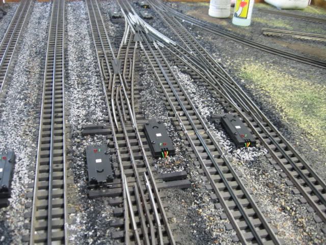
Between the two switch motors to the right are two isolated sections for the (3way) switch pictured.  Note the small white piece of styrene used when the Gargrave track was cut to provide the isolated section. The isolated sections are non-derail inputs for the left "Y" and the right "Y" of this three way switch.  Note that the two isolated sections are staggered, you need outside rail common via the train axle to activated the non-derail.  Two isolated sections across from each other would not work.

 Usually this input location works well for quick-acting snap switches.  Slow moving tortoise switches may require either slow moving trains through the switch or as you suggested moving the non-derail input back away from the switch frog.

Thanks,

Mike Monjure


Last edited by Mike CT
Originally Posted by electric_express_200:

Sorry - One more question, when the derail is detected and it throws the switch, does it continue to pulse the switch each time a trailing car hits the isolated rail and if so, is there a way yo prevent that?  Usually the time delay built into the board will inhibit the pulsing and protect the switch motor from burn-out do to extended power.   


Using the 6931 circuit board either stand alone or with the 6924 will provide the most accurate indication of the route the switch is set to. If by accident a switch motor is thrown by hand (pushing the small lever on the coil to move the switch throw) it will never be indicated by the 6924 circuit board. The design of the 6931 will always be correct as to the present switch setting where the 6924 will never show a switch that has been by accident or purposely thrown by hand.

Originally Posted by Mike CT:
Originally Posted by electric_express_200:

Stewart - Just starting to wire my layout and am practicing on a couple of 072 atlas switches joined to form a simple (and short) siding.  I have the 6924 non-derail board and a dwarf signal kit 6931 which comes with a circuit board.  After looking at the Atlas wiring instructions for this combination, it appears I do not need the board supplied with the 6931 kit because I should be able to control the dwarf signal directly from the 6924 - J3.  Can you confirm this? That is correct, be sure to enable jumper JP1.   Com1/C1(1)/C2(1)Terminals can not be used for anything else.


I used the small boards provided with the 6931 dwarf lights for two reasons.

(1.) My 6924 boards are centrally located. It was easier to hook the 6931 dwarf lights directly to the switch motor as the diagram shows.

(2.) By not using the Com1/C1(1)/C1(2) relay for the dwarf lights, it was still available for power routing.  Some of my switch cross over combinations required the used of both relays on the board, there were two track circuits involve in the cross over.


A few more questions - The instruction say the 6924 will work for 2 switches, but I don't think I see how to wire a second switch (Paired cross over switches (2)), is where this function is normally uses.  Both switches have to be either diverged or straight at the same time.  The Outputs from the 6924 board can power both switches at the same time either Through or Out. It is interesting to note that You will probably not have to hookup the diverge non-derail input for a very short cross over.     and last, if I am reading the diagram right, I must connect 2 wires to the isolated rails right near the switch convergence, which seems like last second switching when the derail detection occurs.  Is there a way to move detection out further with an isolated rail prior to actually getting on the switch track?  Yes, You can cut an isolated rail section further back on the track.

Between the two switch motors to the right are two isolated sections for the (3way) switch pictured.  Note the small white piece of styrene used when the Gargrave track was cut to provide the isolated section. The isolated sections are non-derail inputs for the left "Y" and the right "Y" of this three way switch.  Note that the two isolated sections are staggered, you need outside rail common via the train axle to activated the non-derail.  Two isolated sections across from each other would not work.

 Usually this input location works well for quick-acting snap switches.  Slow moving tortoise switches may require either slow moving trains through the switch or as you suggested moving the non-derail input back away from the switch frog.

Thanks,

Mike Monjure


Thank You!  I do think I get the staggering, if you do not stagger the cuts, it would effectively open the circuit.  I assume that your inputs to the 6924 are connected between the 3 way switch and the isolation cuts, correct?  And just to be sure, their is no cut at all on the center rail?

Originally Posted by Jim M:

Just to make sure, are these the correct locations for the J1 - 1a and 1b leads to connect and do I need insulated rail joiners where indicated?


Though technically the answer is yes, you don't have to limit the size of the isolated section to the size of just one piece of track.  You can add another section of track and then place an insulated rail joiner on that piece of track.  You can make that isolated section of track as long as you want.  A longer section of isolated track will limit how often the circuit board relay trips.  If you just have a short section of isolated track, the relay trips every time a new truck passes onto that isolated section.  

Great - I got it to work.  Just need to determine the optimal length of the isolation sections!  Thanks everyone who helped shorten my learning curve :-)

Originally Posted by electric_express_200:
Originally Posted by Mike CT:

Note that sometimes the rails marked in the picture can touch the frog.  Be sure that the rail sections are isolated. 

Yes, thanks.  I think this has been the source of my problem.  They are connected and the drawing on the Atlas diagram shows them as isolated.  Should have checked with a meter right out of the shoot.

You're welcome

Mike CT


Originally Posted by ChessieFan72:

Hey Gang,


I'm editing the post to make this tutorial a little more user friendly. This tutorial will assist in wiring the Atlas 6924 non-derail board with the Atlas #57 switch control. It will not cover powering the closure rails. I'll be breaking down the wiring into two parts covering power and common, and isolated rail detection and switch machine control. I'll also include a testing and troubleshooting section at the end should you encounter any problems as I did.


The wiring will follow Atlas' schematic with the following exceptions: the color of the wires will be different and all power will come from the accessory side of the transformer.


Materials Used

  • Atlas 6924 Non-Derail Board
  • Atlas #57 Switch Control Box
  • Atlas #312 5 Conductor Ribbon Wire
  • Barrier Strips

The 5 conductor ribbon wire is optional, but I found very useful. It provided 5 different colors which made keeping track of each wires function easier and helped reduce any confusion during wiring. The barrier strips are also optional. This was a personal decision of mine as I found it easier to assist in troubleshooting rather than splicing wires together and then having to undo the splice.


Wire Reference

  • Power - Red (exception: red wire running from the switch motor to 6924)
  • Common - Black
  • Isolated Rail Detection and Direction Control -Blue and Yellow
  • Switch Motor - Red and Green
  • Switch Motor Common - Black 

The color scheme was changed to fall in line with my layout wiring in which red is used for power and black is used for common. It made more sense to me that if I were holding a red wire, it was meant to power something. If you already have a layout built and used different color wiring, simply substitute your wiring color scheme.


Wiring Power and Common


In order to operate, the 6924 n/d board requires a power supply of 6v - 22v AC/DC supplied to J6. I chose the accessory side of my transformer for all power inputs into the 6924 to eliminate the need for a second power source.


Power (red) is routed to the following terminals:

  • 6924 terminal J1 - SW PWR IN
  • 6924 terminal J5 - COM 2
  • 6924 terminal J6 - PWR

Common (black) is routed to the following terminals:

  • 6924 terminal J6 - COM
  • #57 Switch Control terminal labeled C - Take special note and care when wiring to the #57. Connecting to the posts with the red X will damage the 6924 n/d board.
  • Switch Machine terminal labeled BL

This tutorial only covers the use of one 6924. The 6924 can be daisy chained to supply power to additional 6924's. To enable this function, install the jumper on JP 1. refer to the Atlas instructions for further wiring. 


pwrcomwiring


Isolated Rail Detection and Switch Machine Control


Through Route Detection (Yellow)


The through route isolated rail detection wire and the wire from the #57 switch control terminal labeled 1 will be connected. (In my case, I used a barrier strip.) The connected wires are then run to the 6924 terminal J1 IN A. Next, connect the #57 switch control terminal labeled 3 to the 6924 terminal J5 C1-2.


Diverging Route Detection (Blue)


The diverging route isolated rail detection wire and the wire from the #57 switch control terminal labeled 2 will be connected. The connected wires are run to terminal J1 IN B. Next, connect the #57 terminal labeled 4 to the 6924 terminal J5 C2-2.


Switch Machine Control (Red, Green)


Connect the wire from the switch machine terminal labeled G to the 6924 terminal J4 OUT A. Connect the wire from the switch machine terminal labeled R to the 6924 terminal J4 OUT B.


detectionandcontrol


Testing and Troubleshooting


Before turning on the power supply, ensure the power is set to within the 6v - 24v range. (Since I am using TMCC, my power preference is 18v to keep things logical and in order for my taste. The transformers I will be using allow me to set a custom voltage. Other transformers may have a set output. Just ensure it is within range.)


Turn on the transformer and look for the LED located on the 6924. If it is lit, the 6924 is receiving power. If it is unlit, check for proper voltage and any loose connections.


Set the #57 Switch Control for the through route*. Move the lever to N** and press the activation button. The green indication light should be lit. If the red indication light is lit, reverse the wires to the 6924 terminal J5 C1-2 and C2-2. Cycle the #57 Switch Control by moving the lever to R**, press the activation button, and then move the lever back to N and again press the activation button. Once the green light is synced, check the points of the turnout. The points should be aligned as follows: green indication light with the through route and red indication light with the diverging route. If the points and indication lights are out of sync, reverse the wires to the 6924 terminal J4 OUT A and OUT B.


* The through route is the route the train would normally travel. In most cases, the through route would have the points set to straight and the diverging points would be turned out. In some cases, the modeler uses the points turned out as the through route and the points set as straight for the diverging route.


** For those of you asking what the N and R stand for, I had the same question and did a little investigating. N  "Normal" is the main track route and R "Reverse" is the diverging route. If you are looking for more information on CTC control, would like to build your own CTC panel, or want to look at some eye candy, the CTC Parts website is a great read.


This is probably a dumb question, but you say that you are using barrier strips to join common connections and I totally get that.  But being as they are barrier strips, some of the drawings show multiple wires in and one out, i.e. the common on your PS.  I would think this would be more like a terminal block unless you are jumpering some of the individual strip terminals to each other.  I am looking to do set up exactly like this, but cannot find any reasonably sized terminal blocks aside from the gargantuan (and expensive) MTH terminal blocks.  Any advice?

Good morning everyone. I am beginning to wire the 6924 board(s) and #57 switch controllers. Several questions have come up that I can''t find the answers for,

so I'm looking for some help.


1)  I would like to connect the # 57 switch controllers together using the jumpers

     supplied with the controller. The Atlas diagram shows connecting both the 

     upper and lower right hand connections to the upper and lower left hand 

     connections using the jumpers. In one of Stewart's bullet points it's stated

     "Take special note and care when wiring to the #57. Connecting to the 

     posts with the red X will damage the 6924 n/d board". How would you

     connect the #57 controllers to not damage the 6924 n/d board?


2)  I would like to daisy chain the  power supply for 6924 n/d boards together.

     A second bullet point states this requires that the jumper on JP 1 be

     installed. I understood that connecting JP 1 activates J3, used for adding

     a dwarf signal and that j6 is independent of JP 1. Do I need to install the

     jumper to daisy chain the power supplies?


3)  In addition to utilizing the non-derail function, I also want to power

     the closure rails. The wiring diagrams indicate that J5 is used to

     connect the power closure rails and connect to the #57 switch controller.

     Can this be done? Do I utilize a separate jack ie: J2? Atlas states that

     connecting power to J2 Com 1 when the jumper for JP1 is installed wlil

     damage the 6924 n/d board. (See question 2)


Last and most importantly, I want to really thank Stewart for the work on this

post. Your diagram and description have been able to help me understand how

to wire the board and switch controller. Mike


Stewart, the above is great and super helpful.  About to start wiring up my #6924's to my #57's.


QUESTION #1)  Is the below diagram from Steve still OK to use if you have, ie., smaller switch's, 0-36 to 0-54, where trains cruise through fine.  Another way to put it is......does the BLUE / YELLOW Power Routing rails really need to be wired back to #6924 if trains go through switch without stalling, OR does the power routing wires actually active the Non-Derail feature?


QUESTION #2) Looks like CT Mike has 3 Amp fuses on his #6924's.  Necessary or just extra insurance?  If really needed not sure how those are wired.


QUESTION #3:  J 6 COM & POWER:  6-22VAC/DC.  Does this go back to Accessory Post on my KW OR....... is this the link/daisy chain to next #6924?


Thanks!  Mark


57WITH6924WIRING

Attachments

Images (1)
  • 57WITH6924WIRING

QUESTION #2) Looks like Mike CT has 3 Amp fuses on his #6924's.  Necessary or just extra insurance?  If really needed not sure how those are wired. 


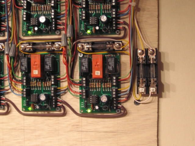
My track circuits were fused at 7.5 amps.  The 6924 boards are rated at 8 amps, I still had issues burning power routing traces on the boards, and added the 3 amp fuses.  Power routing is not a refined art, there are a lot of wheels and axles moving through relatively small electrical clearance areas.  I do replace the 3 amp fuses on occasion, much easier than replacing the boards.

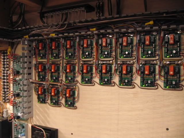
Note the fuses, some boards have two track circuits, (two fuses), involved in multiple switch, multiple track cross-overs. Fuse is installed in the track power circuit that feeds the small dead rail sections center of switch through the board.  The fuse is shown on the Atlas power routing detail.   Click on the underlined phrase.  Note that the 6924 boards will handle two switch motors when switching two as a cross-over pair.  My layout has (21)  6924 boards, controlling (25) switches, there are (4) cross-over pairs.


QUESTION #3:  J 6 COM & POWER:  6-22VAC/DC.  Does this go back to Accessory Post on my KW OR....... is this the link/daisy chain to next #6924?

In the picture, the brown (2) conductor 18 ga. thermostat wire at the bottom of the picture, daisy chains board power between all my 6924 boards.  One accessory circuit powers all the boards.  Green light on the board indicates it's powered.

Last edited by Mike CT

Mike/Steve, thanks for the quick replies.


FUSE:  .....Fuse is installed in the track power circuit that feeds the small dead rail sections center of switch through the board......If I'm not using power routing where would fuse go?  Seems like between KW Power Feed and board J1 SW PWR IN.  Correct?


TERMINAL BLOCKS:  Per Stewart's post he is using Terminal Blocks.  Don't see them on your board Mike....although they may be above the picture wiring.  If Terminal Blocks are used like Stewart's can I feed, ie., multiple 6924's into the same Terminal Blocks to cut down on space/adding more blocks?  Basically ie., sending, ie., 4 set's of wires from 4 separate 6924's to respective Terminal Block poles, etc.


Mark

Originally Posted by Mark B:

Mike/Steve, thanks for the quick replies.


FUSE:  .....Fuse is installed in the track power circuit that feeds the small dead rail sections center of switch through the board......If I'm not using power routing where would fuse go?  Seems like between KW Power Feed and board J1 SW PWR IN.  Correct?


TERMINAL BLOCKS:  Per Stewart's post he is using Terminal Blocks.  Don't see them on your board Mike....although they may be above the picture wiring.  If Terminal Blocks are used like Stewart's can I feed, ie., multiple 6924's into the same Terminal Blocks to cut down on space/adding more blocks?  Basically ie., sending, ie., 4 set's of wires from 4 separate 6924's to respective Terminal Block poles, etc.


Mark

Note the J6 terminal is designed with (2) PWR (Power) and (2) COM (Common). It is relatively easy to daisy chain multiple boards.


Keep in mind this is only board power, does not account for any track power required for power routing, note the 3 amp fuse.


SW PWR IN , IN A, and IN B are also external power sources, eventual working through the board to Out A and OUT B to the switch motor.

Last edited by Mike CT
Originally Posted by Steve Horvath:

Mark,

You only need one fuse for all the 6924s. Install it inline from the power lead to the first 6924. Then add additional wiring to each 6924 (daisy chain).If you want I can be reached at Atlas. Call 908-687-0880 and ask the operator to page me.

Hi Steve/Mike....I've got 4 boards wired and working well!  


FUSE: When you say install inline from the power lead to first 6921 you are referring to J1 PWR IN....correct?


Instead of daisy chaining power I'm doing this.....I have an MTH Buss Board, the green one, with 12 red/black posts.  My KW power, from the accessory post, and common, go 1st to the MTH Buss Board.  Power and Common for each 6924 runs from MTH BB Post 1 to Board 1, Post 2 to Board 2, and so on.  I could put fuse between MTH BB Power and KW.....that would work?  


I know I could cut down on wiring if I daisy chained all the J1 PWR IN's. At present, for each 6924, I have the below 3 J's wired together with wire nut.

  • 6924 terminal J1 - SW PWR IN
  • 6924 terminal J5 - COM 2
  • 6924 terminal J6 - PWR

Will send picture!

Originally Posted by Steve Horvath:

Mark,

You only need one fuse for all the 6924s. Install it inline from the power lead to the first 6924. Then add additional wiring to each 6924 (daisy chain).If you want I can be reached at Atlas. Call 908-687-0880 and ask the operator to page me.

 Per my post tonight here are 2 shots of my work.  Per the post need to confirm fuse placement and daisy chaining the J1 PWR.

Atlas 6924 i

Atlas 6924 ii

Attachments

Images (2)
  • Atlas 6924 i
  • Atlas 6924 ii

Well Done, a few comments, via observation of your work/photo.


Left side of board(s).

(1.) Blue (J1) wire is SW PWR IN. J1 terminals

(2) Green (IN A) (J1) and Red (IN B) (J1)  would be Through and Out push buttons, also used for automatic non-derail input feature.

(3.) Not shown, I assume that all blue input wiring is fused.

(4.) (3) relay terminals not used (J2) middle left side are a second relay that can do two things:

One, as wired, it logically powers the three small plug-in terminals bottom left that can be used for dwarf lights.

Two, remove jumper JP, it can be use as an additional power routing relay.


Right side of board(s)

(4.) Green (OUT A) (J4) and Red (OUT B) (J4) wires top terminal, would be wired to the through and out terminals on the switch motor.

(5) Blue in, from the right, would be Track Power to an available relay that will Power Route, dead rail track sections of the switch.  It appears that both switch motor power and dead rail track section power are the same power source.

(6) Red and Green are wires that attach to the dead rail sections, center of switch. As wired, this is also fused power, to prevent board damage.  

(7) Yellow and Blue are daisy chained wires that power the 6924 relay boards.   


Comment:

As wired, if your fuse blows, you will loose all switch motor(s) function,  If you fuse each 6924 board/switch motor separately, you will only loose that switch motor if the fuse blows. Fuse/over current protection is not shown in these pictures.

Atlas Power Routing/6924 relay board wiring from the Atlas website.

Best wishes  

Mike CT   

Last edited by Mike CT
Originally Posted by Mike CT:

Well Done, a few comments, via observation of your work/photo.


Left side of board(s).

(1.) Blue (J1) wire is SW PWR IN. J1 terminals

(2) Green (IN A) (J1) and Red (IN B) (J1)  would be Through and Out push buttons, also used for automatic non-derail input feature.

(3.) Not shown, I assume that all blue input wiring is fused.

(4.) (3) relay terminals not used (J2) middle left side are a second relay that can do two things:

One, as wired, it logically powers the three small plug-in terminals bottom left that can be used for dwarf lights.

Two, remove jumper JP, it can be use as an additional power routing relay.


Right side of board(s)

(4.) Green (OUT A) (J4) and Red (OUT B) (J4) wires top terminal, would be wired to the through and out terminals on the switch motor.

(5) Blue in, from the right, would be Track Power to an available relay that will Power Route, dead rail track sections of the switch.  It appears that both switch motor power and dead rail track section power are the same power source.

(6) Red and Green are wires that attach to the dead rail sections, center of switch. As wired, this is also fused power, to prevent board damage.  

(7) Yellow and Blue are daisy chained wires that power the 6924 relay boards.   


Comment:

As wired, if your fuse blows, you will loose all switch motor(s) function,  If you fuse each 6924 board separately, you will only loose that switch motor if the fuse blows.

Best wishes  

Mike CT   

Thanks Mike!


LEFT SIDE#3:  No fuses yet.  That's why I left each 6924's BLUE WIRES a bit longer wired with BLUE NUT.  

----- Can I put a fuse between KW power and my MTH Buss Board, see where my finger is pointing for fuse location on MTH BB Picture.....1 fuse at the beginning of whole thing.....OR.....Fuse before J1 PWR for EACH 6924?


Per my post, I'm running a PWR BLUE LINE and COMMON YELLOW LINE from each MTH Buss Board post(s) over to each 6924, combining all the BLUE wire's for each board with BLUE WIRE NUT.  Am I over wiring?  I.E., should I be just daisy chaining all these BLUE POWER wires with a fuse before each J1 PWR?

Atlas 6924 MTH Buss Board

Attachments

Images (1)
  • Atlas 6924 MTH Buss Board
Last edited by Mark B

LEFT SIDE#3:  No fuses yet.  That's why I left each 6924's BLUE WIRES a bit longer wired with BLUE NUT. 

I'm more concerned about fusing the Right side J5 terminals used for power routing. As the wheels move through the power routed switch a dead short will damage the relay board.  

----- Can I put a fuse between KW power and my MTH Buss Board.....1 fuse at the beginning of whole thing.....OR.....

Fuse before J1 PWR for EACH 6924?  I do have switch motor circuits fused separately, which, as Steve mentioned, protects the switch motors.  One of the original problems, was stuck buttons, that fried the switch motors. The time out feature, that is built into the 6924 board also protects the switch motors from burn-out.


J5 terminal(s) used for power routing.  This definitely needs fuse protection, track/wheel/derails on a power routed switch can damage the board.   The Atlas diagram shows the (3amp) fuse.  


Per my post, I'm running a PWR BLUE LINE and COMMON YELLOW LINE from each MTH Buss Board post(s) over to each 6924, combining all the BLUE wire's for each board with BLUE WIRE NUT.  Am I over wiring? No, you are doing fine.   I.E., should I be just daisy chaining all these BLUE POWER wires with a fuse before each J1 PWR?


(1.) J1 PWR, only supplies power to the Atlas Switch motor, through the 6924 board.

          Fuse protection here is for the switch motor, to inhibit burn out.

(2.) J6 COM/PWR  supples power necessary for the board to operate and if you use dwarf lights via the J3 terminal it would also power these dwarf lights.

          Fuse protection here protects the board and the dwarf lights.

(3.) J5 terminal, used for power routing. 

          Most important fuse. The nature of moving wheels through a switch/dead  rail section is not a refined accurate art form, at times, there are short circuits here, if power routing is used. I have experience burned traces on the 6924 relay boards associated with the J5 terminal and power routing, the reason for adding the (3 amp) fuses shown on the Atlas diagram.


Best wishes

and again a very good job.

Mike CT.    

Last edited by Mike CT
Originally Posted by Mike CT:

A good location for a fuse, it would protect just about every thing in this discussion. Try it, see how it works for your operation. You may want to revisit this thread and tweak the fusing/fuse location(s) later.

Thanks Mike.  Very helpful comments!!!.  Excellent thread. One the fuse's, I think I will try this....in the following order of installation:

1)  7.5 AMP Fuse at MTH BB Blue PWR line in form KW.  Is 7.5 correct?  sounds like this will protect everything downstream.

2)  J5 COM 2: 3 Amp per atlas diagram.  Do I need this since I'm NOT using Power Routing wires on most of my switches (036-054).

         ---2 Sets of 072 switches for moving trains from my A line/loop to B line/loop. Will these need power routing?  will of course be wiring them in pairs like your #17 & #18 switches.


Add Reply

Post
×
×
×
×
Link copied to your clipboard.
×
×