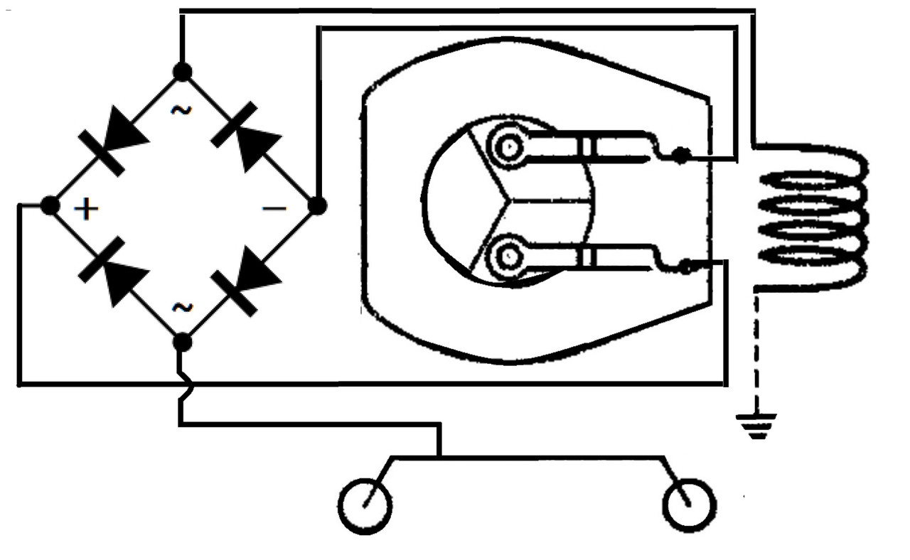
I probably am reinventing the wheel for the millionth time, but I just had to try to figure this out on my own. I may be way off, and maybe at least I will give some forum members a good laugh on me!!! I lifted the pic from @ADCX Rob post in a different thread, and replicated/edited to make the attached pic.
I have watched the "I Love Toy Trains" show on the RFD channel many times. One episode had an operator that said he operated his Lionel postwar engines with DC (in usual three rail power distribution of one polarity to center rail, and other polarity to outside rail). He said he converted the engine by removing the e unit and adding a bridge rectifier, and this allowed him to control direction by the polarities he supplied to the rails (ex, DC plus to center rail, DC ground to outer rail, go forward - DC ground to center rail, DC plus to outer rail, you go forward).
I decided I had to try and figure out what he did, as he never showed a schematic. So the pic I have attached depicts, on the upper left side, how the AC power goes from roller to ground for one direction, and lower left side, how the AC power goes from roller to ground for the opposite direction. I noticed that in either direction, the current going through the field coil is the same for both directions, ie. when the AC is at plus max voltage, the current in the field coil is always going "down" regardless of the direction of the loco.
So on the right side of the pic is my schematic converting the loco to DC power/direction control. The bridge rectifier always keeps the current in the field coil going in the same direction irregardless of the polarity of the DC being applied to the motor.


