As many of you know I am thinking about expanding my layout.  I am thinking about building only a 2 feet by 8 feet extension.  Was thinking about having it elevated.  I only want to raise the elevation about 2 or 3 inches.  Was wondering what people use for pilings or any other method to raise the track and use possible trestle or super structure.  Thanks!

Original Post

Replies sorted oldest to newest

To change track elevations I used a ramp, using a sheet of 1/2in plywood , I measure the track width and cork roadbed and added a 1/4 in both sides, i.e., 1/2 inch to this width, for your elevation of 2 inch and width draw two parallel lines the width apart for 57-9/32 inches long with a jig saw, for the 3 inch elevations do the same procedure but the length is 86-1/16 inches long. The ramp is a right triangle, the vertical (opposite) leg is the elevation, 2 or 3 inches, the angle of elevation is 2 degrees. The adjacent leg is the base of the triangle, from trig the Tan of the angle= the rise (elevation) divided by the base, the ramp is the hypotenuse, to solve for the base divide the rise by the Tan of 2 degrees. Now having the rise and base square both add these two squared values together and take the square root of this number, this is the hypotenuse or ramp length for an angle of 2 degrees. When you cut these two parallel line a constant width apart you will lift up this segment for a ramp. Use can use a truss frame bridge, pilings supporting a wood deck with track attached, or a wood trestle supporting wood deck with track. If you need assistance on the trig I will do the calculation and fax it to you tomorrow.
Thank you for that information.  That is extremely helpful!  I myself got a headache trying to figure out what i need to do!  LOL  I will read this a few more times and try to get my teeth around it!  Once again thank you.
 
 
Originally Posted by John Ochab:
To change track elevations I used a ramp, using a sheet of 1/2in plywood , I measure the track width and cork roadbed and added a 1/4 in both sides, i.e., 1/2 inch to this width, for your elevation of 2 inch and width draw two parallel lines the width apart for 57-9/32 inches long with a jig saw, for the 3 inch elevations do the same procedure but the length is 86-1/16 inches long. The ramp is a right triangle, the vertical (opposite) leg is the elevation, 2 or 3 inches, the angle of elevation is 2 degrees. The adjacent leg is the base of the triangle, from trig the Tan of the angle= the rise (elevation) divided by the base, the ramp is the hypotenuse, to solve for the base divide the rise by the Tan of 2 degrees. Now having the rise and base square both add these two squared values together and take the square root of this number, this is the hypotenuse or ramp length for an angle of 2 degrees. When you cut these two parallel line a constant width apart you will lift up this segment for a ramp. Use can use a truss frame bridge, pilings supporting a wood deck with track attached, or a wood trestle supporting wood deck with track. If you need assistance on the trig I will do the calculation and fax it to you tomorrow.


A rule of thumb is that 1/4" in 12" or a foot is ~ 2% grade (actually a 2.08% grade).  So a 1% grade would be 1/8" in a foot, and a 3% grade would be 3/8" grade. 


One thing to remember is that grades go both up and down.  I have an around the room layout and wanted to put some hidden staging underneath on long side.  I wanted 8" vertical separation between the two levels.  This results in a net clearance of 6" (8" - 1/2" track - 1" plywood rib - 1/2" homasote).  I only had 12 feet to achieve the 8" which would mean a 5.6% grade.  By going up and down 4" we cut the grade in half to a more manageable 2.75%.


Jan

After my response yesterday I was considering what the bridge will span, span length, and whether the bridge is single or double tracked. If you are spanning a road at 3 inch elevation I would consider using a wood deck trestle bridge with wood framing either side of the road to the bottom of the deck or a plate girder bridge sitting on abutments. If you are spanning a stream, river or shallow wash then you can use pilings. My track layout has two elevations, 6 inch and probably 14 inches over the base plywood, spans are 2 and 3 feet, and double tracked, I use a plate girder bridge for the 2 foot span and truss bridges for the 3 foot span, these bridges sit on abutments cut from wood and painted a gray color to simulate concrete. The bridges, whatever type, look good on the layout especially with a train passing over them. Carstains published a book on bridges and so did Kalmbach Publishing, these may be available on the web. Also if you do a general search on the web, there should be sites for bridge type and construction. I scratch built the truss and plate girder bridges using the Kalmbach book as a reference form bass wood and Elmers wood glue, be careful, staining wood glues may or may not be possible, I painted my bridges flat black.

Grades can be a bit of a problem with smaller layouts.  Using 12 ft (144 inches) as a possible run and an acceptable rise of 5 or 6 inches (overpass, underpass, or two different levels of a layout.  % grade = rise/run X 100  5/144 X 100= 3.47%.   


That's one grade, usually an up and down grade are require. In this case you would need 24 ft of track

My grades bend around corners to get to 12 ft.
Last edited by Mike CT
What I was hoping to do is possibly install something out of the back towards the wall that would be spaced so that I wouldn't need to build or place a whole sheet of plywood.  I was thinking of having of a height of about two or three inches.  I only have 4x8 layout.  I am only looking to just add some height so that the locomotive in the back loop doesn't disappear.  I debating weather or not to have a viaduct or something of a truss style bridge.  The information given earlier is extremely helpful.  I am just trying to compute what I need?  I would not mind having one long superstructure in the back and just pilings on either side.  I am still playing with some ideas. 
 
 
Originally Posted by Mike CT:

Grades can be a bit of a problem with smaller layouts.  Using 12 ft (144 inches) as a possible run and an acceptable rise of 5 or 6 inches (overpass, underpass, or two different levels of a layout.  % grade = rise/run X 100  5/144 X 100= 3.47%.   


That's one grade, usually an up and down grade are require. In this case you would need 24 ft of track

My grades bend around corners to get to 12 ft.


New%2520Layout


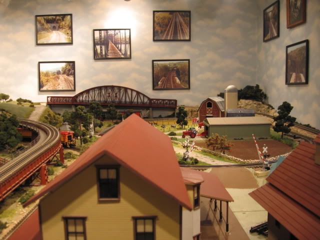
Mike, I also want to say what an amazing layout you have!

Attachments

Images (1)
  • New%2520Layout: An old picture
Last edited by jjmmagoo

Add Reply

Post
The Track Planning and Layout Design Forum is sponsored by

AN OGR FORUM CHARTER SPONSOR

OGR Publishing, Inc., 1310 Eastside Centre Ct, Ste 6, Mountain Home, AR 72653
800-980-OGRR (6477)
www.ogaugerr.com

×
×
×
×
Link copied to your clipboard.
×
×