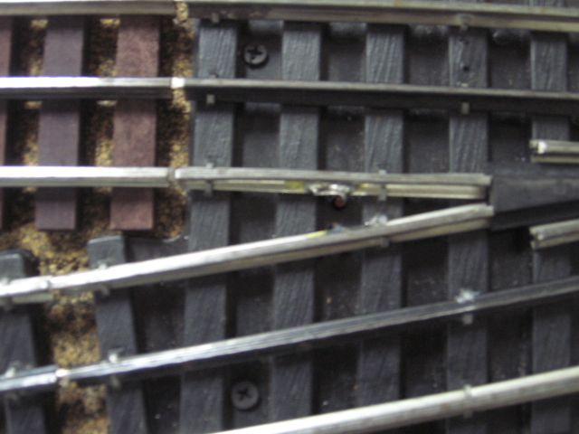
Some notes on this discussion.
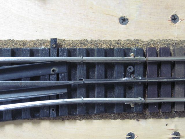
This is a used Gargraves switch there are (3) black rail center pieces that are not wired together. Upper left, Lower left and center right. The switch is a used switch and a small piece of green wire was added, center of picture, to connect center rail pieces
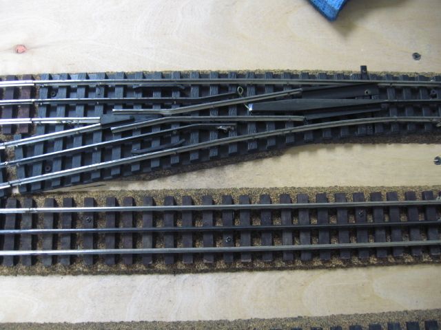
Power was added upper left. Note the solder connection on the section of track, to the left, connected to the switch.
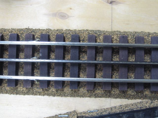
Power was added lower left. Note the solder connection to the switch black center rail near the frog.

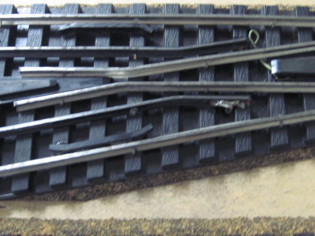
Center right connection. Near the track screw in the switch.
Ross Switches, that are not "Ross Ready", would require the same connections.
Also note that to do automatic, electric, non-derail switch motor wiring. (2) additional wires are added at the short, (isolated rail pieces near the switch frog). Plastic isolation pins were added at these outside rail connections.
