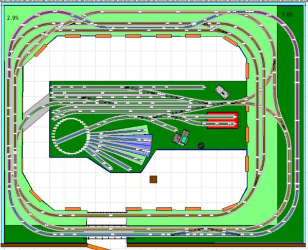
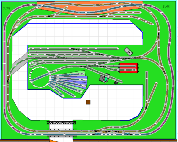
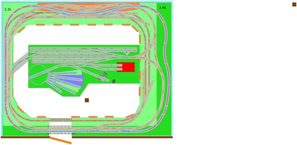
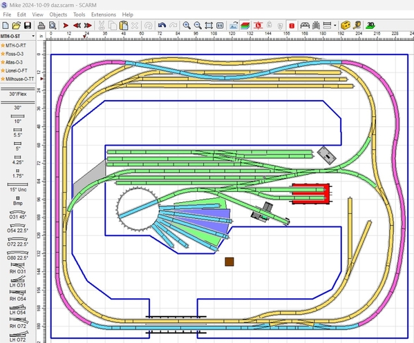
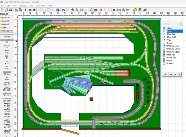
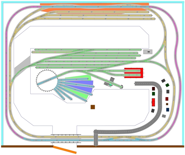
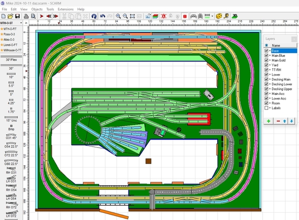
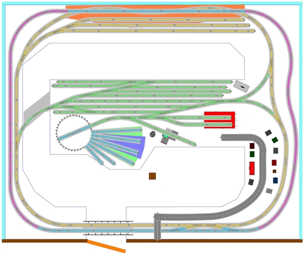
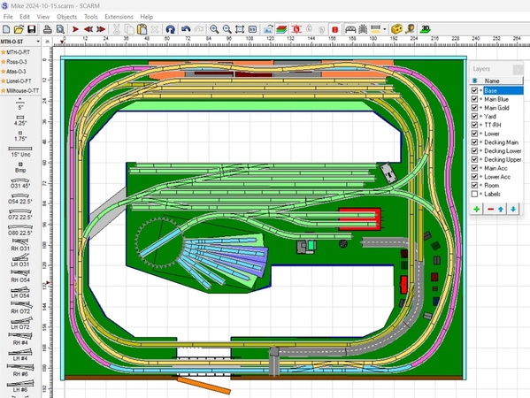
Hi Folks I am working on my future layout and have came up with a plan, but am in need of some help for placement of my inter model container yard. also I want to be able to put a city or town in place, but I am drawing a blank ! any help would be great below it a plan of my future layout!

The layout will have a lower level with 1 loop, the main level will have 2 loop with one going up along the back.

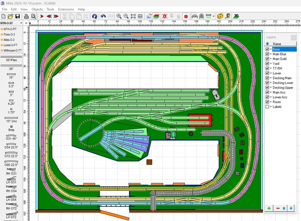
I have attached the SCARM file for those who use it, if not feel free to draw all over the plan! LOLScreenshot 2024-

Attachments

Images (1)
  • Screenshot 2024-
Files (1)
Original Post

Replies sorted oldest to newest

Hi Jan and Dave, I think you both came up with a great idea! I just needed a place to operate a intermodal crane and have room to store some containers!

I think the end to the right will be a good place to start my town/city and blend into  my industrial area as I go along that Right wall towards the back wall.

Once again I am open to thoughts!

Hey Mike,

Not sure this will work, but I'd lose the spur at the bottom right and use that large area for your town. You could add a small spur or two at the bottom as shown if you need to.

I'd also straighten out the double main lines at the top so they resemble the bottom configuration and eliminate one or two of the long spurs and use that area for your intermodal operations - maybe a gantry crane, dock, oil refinery, etc - things that are wide but not too deep. Not sure what curves you are using but you might be able to tighten the curve at the left to form the one long spur along the bench work to give more space for the intermodal area.

I'll leave the design work to Dave and Jan, but just my $ 0.02

Attachments

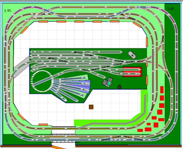
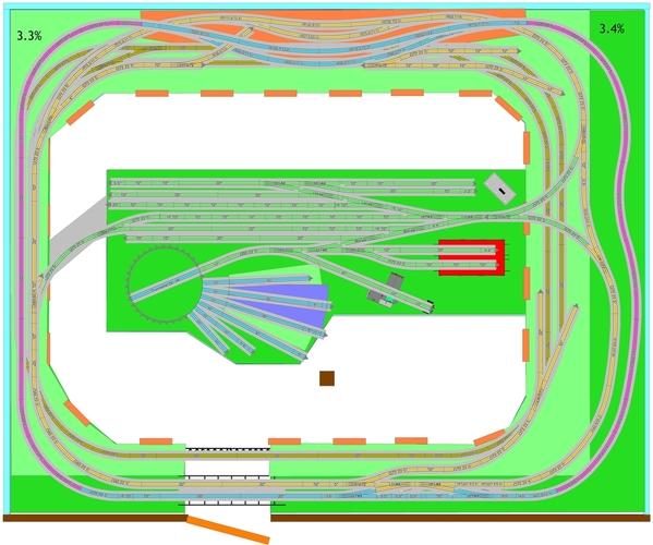
Ritchie, the spur was supposed to be for a town, so I replaced it with a road and added some buildings that I was able to "borrow" from other designs. Work had been ongoing since mid May. One druther was meandering curves and over/under sections. Adding the intermodal yard is new, so I straightened the Blue line and the yard won't be covered. The main decking ends where the yard ends so as not to completely cover the passenger station section on the lower level. The "blocks" you see are intermittent subway walls to partially block the view of the subway.

t1

Mike, here's are views of the main level. The intermodal yard can be changed, I just don't have a crane, etc.

t2

The empty area below the intermodal yard is part of the lower level where you wanted to be able to look in to see the passenger station, etc. The main level decking can be expanded and the yard moved down some, but you'll lose visibility of the station unless you really bend over.

Mike 2024-10-09a daz

Attachments

Images (3)
  • t1
  • t2
  • Mike 2024-10-09a daz
Files (1)

After looking over Jan's version, I noticed a few things that were "off". I didn't go back to look, but they've been off for a few versions.

Anyway, the main thing was that the TT/RH was out of place and I was concerned the footprint had gotten skewed. So, I found my original 4-stall RH with the footprint rectangle and replaced what was there to go with the 28" TT. This is something that really needs to be double-checked, test fitted, etc., before installation.

The coal and water towers were also out of place, so I moved those. And the windows on the control tower are on one side, so I reoriented that so employees could see down the yard. Obviously, those things all depend on the specific accessories.

I also recorded a short operating session.

Mike 2024-10-11 daz

Attachments

Images (1)
  • Mike 2024-10-11 daz
Videos (1)
Recording 2024-10-11 100505
Files (1)

Hi Mike,  You new train room is coming along very well!  Something you mentioned early in this topic about the post limiting the geometry of your layout piqued my curiosity.  I found your reply in the What did you do on your layout today topic (linked here)> https://ogrforum.com/topic/121...5#185988372325405255

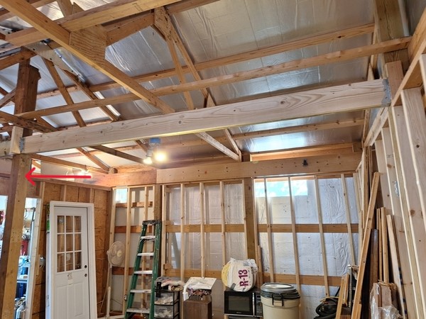
It shows this photograph.

20241010_160407-mu

Is the post on the left (indicated by the red arrow) the same as the one depicted in the layout design?  If so, you may want to consider these questions while you're still in the room construction phase.

The post and beam construction appears to carry the entire roof load at the ends of the trusses.  Looking at the truss design, the center post doesn't seem to be supporting a load at the moment.  Are you planning to add some kind of load later that would require the post to be there?

If not, could that center post be removed to eliminate the obstacle in the center of the room, giving more layout space and flexibility?

Attachments

Images (1)
  • 20241010_160407-mu
@SteveH posted:

Hi Mike,  You new train room is coming along very well!  Something you mentioned early in this topic about the post limiting the geometry of your layout piqued my curiosity.  I found your reply in the What did you do on your layout today topic (linked here)> https://ogrforum.com/topic/121...5#185988372325405255

It shows this photograph.

20241010_160407-mu

Is the post on the left (indicated by the red arrow) the same as the one depicted in the layout design?  If so, you may want to consider these questions while you're still in the room construction phase.

The post and beam construction appears to carry the entire roof load at the ends of the trusses.  Looking at the truss design, the center post doesn't seem to be supporting a load at the moment.  Are you planning to add some kind of load later that would require the post to be there?

If not, could that center post be removed to eliminate the obstacle in the center of the room, giving more layout space and flexibility?

Hi Steve, that post with the red arrow is the one that I have been talking about. It was originally the back post for a 20' X 20' shop. At some point they added another 12' and put in another end post. I haven't thought about taking it out because it anchors both the end of the old section and the beginning of the newly added on section.

To be honest I don't know if it is doing anything or not! LOL

Last edited by mike g.

Granted, I'm not seeing the whole picture of the framing, but based on what I can see, if it were my building, I'd consider replacing the 2x6s (the ones attached to the centerline posts with Joist hangers/brackets) with something up higher.  Perhaps running end to end below and parallel to the roof centerline and attached to the top of the trusses' bottom chords.  Then take out the center post.  Just to be sure, I'd check with your building inspector first, assuming you already have a construction permit.

Last edited by SteveH
@SteveH posted:

Granted, I'm not seeing the whole picture of the framing, but based on what I can see, if it were my building, I'd consider replacing the 2x6s running between the center posts with something running end to end below and parallel to the roof centerline and attached to the top of the trusses' bottom chords.  Then take out the center post.  Just to be sure, I'd check with your building inspector first, assuming you already have a construction permit.

I'm going to have to take another look at that!

An another tweak.  I took the spur track next to the turntable and made it another passing/run-around siding.  This will allow easier train building and breakup.  Also the short spur on the left can serve as caboose/rip track.  The yard has become very functional and operations there will be a focal point.

I've never looked hard at intermodal yards so I can't comment on them.  I will say that stations along the mainline will usually have freight house spur for LCL deliveries.  Also industries will have a spur(s) for deliveries and shipments.  So if operations are your interest don't forget them.

Also, thanks to Dave I now know what the buildings in the are.  I did recognize the roundhouse!

Jan

Mike 2024-10-09a daz jan 2

Attachments

Images (1)
  • Mike 2024-10-09a daz jan 2
Files (1)

The yard tracks were too close to the TT and the TT/RH was the old footprint. Again, I don't know (or care) how or when the TT/RH got messed up, but it did and I fixed it in my last version.

Anyway, I added Jan's runaround combo to my latest version, reoriented the TT/RH footprint and yard accessories. I also updated the decking/baseboard. This new orientation assumes a 5" straight to the TT will be enough. The TT/RH is close to impacting the aisleway and can't move any further to the left. There's also now even less space for yard accessories, like the control building and I moved the coal and water stations into new positions. I'm all for storage, but I'm assuming you want somewhat of a prototype yard with some accessories.

Mike 2024-10-14

Attachments

Images (1)
  • Mike 2024-10-14
Files (1)

Good news on the post. Assuming you take it out, we can expand the width of the peninsula by 6" to 5' or a full 18" to 6'. There are some reach concerns for the area just above the RH, so I'd lean toward just the 5' with perhaps a removable 1' section (yellow) for added landscaping. Totally your call.

t

Attachments

Images (1)
  • t

Morning guys I hope you all doing well!

Dave I like the looks of it and I agree I don't want to get any wider then 5' as that will be pushing it for a short guy like me! I can always build a fold up step so it folds under the layout to help reach the center. When I was out there taping off the bench work on the floor I have noticed thing are closer then I expected. Its all my fault as the room size is 15' 4" X 19' 4" because of the 2x4 framing. I can still fit everything its just the isle are a little bit narrower! LOL good thing I started a diet! LOL

@Mark Boyce Mark as for the post it is still standing. I was going to take it down today but the Physical Therapy pretty much kicked my rear this morning! But there is always tomorrow!

Mike, I went through and modified the design based on the new room measurements. As a result, I noticed that the right side of the main level decking was over 36" wide, so I reduced the width. I also made a few other adjustments and, like you, I'm concerned about the width of the aisle on the left. I'm also concerned that there is a switch on the lift-out section and I don't think that's advisable, so I'll be working on those.

Mike 2024-10-15

Attachments

Images (1)
  • Mike 2024-10-15
Files (1)

Won’t argue about how wide is wide enough, that’s for Mike to decide. FWIW, it’s 22" as shown. My bigger concern is the switch on a lift-out/lift-up. I know it can work, just a concern. I also think the upper yard tracks are too close to the edge, so the yard and/or the peninsula needs some adjustment. And the lower tracks and the bridge may also be too close to the edge. If that’s not enough, the curves along the right side might also be too close, I just haven’t fiddled with them much because Mike will do that during construction. I don’t like trying to lay flex track perfectly, just enough to show things can fit.

i Dave & Jan As for the original plan it has not changed, when I taped out the bench work on the floor I kept the bench work the same size. The isle is the only thing that is smaller really. I will double check it again after I get it somewhat cleaned up in there.

As for some good news the post is gone! I will have to repair the hole in the floor but that is ok I have concrete already on hand.

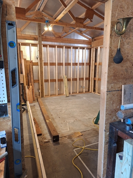
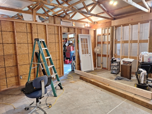
20241016_11212520241016_112138

Attachments

Images (2)
  • 20241016_112125
  • 20241016_112138
@mike g. posted:

Dave I like the looks of it and I agree I don't want to get any wider then 5' as that will be pushing it for a short guy like me! I can always build a fold up step so it folds under the layout to help reach the center. When I was out there taping off the bench work on the floor I have noticed thing are closer then I expected. It’s all my fault as the room size is 15' 4" X 19' 4" because of the 2x4 framing. I can still fit everything its just the isle are a little bit narrower! LOL good thing I started a diet! LOL

@mike g. posted:

i Dave & Jan As for the original plan it has not changed, when I taped out the bench work on the floor I kept the bench work the same size. The isle is the only thing that is smaller really. I will double check it again after I get it somewhat cleaned up in there.


Mike, I went back through the PM thread and the only room size I found was where you posted this comment:
Jeff the final room is 19' 8" W X 15' 8" D.

So, that’s the room size we’ve been working with. Now you’re saying both measurements are 4" shorter, so that’s why I changed the plan by shrinking the room/baseboard those 4".

I know the basic plan will fit and you’ll modify things as needed during the build, but I’d like to get as close as we can in software. I’m mostly concerned with the Wye and peninsula because of the switch on the lift-up and the tracks that are close to the upper edge. I’m also concerned the left side bench work might be too narrow. It was just 12", so I widened it to 14", but want to take another look to make sure there’s enough clearance for the overhang there will be with an engine coming out of the yard and crossing the lift-up. At this point I have no idea what kind of overhang your engines have, but I believe most modelers try for a 6" center-to-center clearance on curves to accommodate larger engines. That might be overkill, but I’d like to see how wide the bench work needs to be for that. With the grade track and dual mains, there needs to be room for 3 tracks and any overhang.

The Wye dictates where the yard tracks go and the size of the wye is dictated by the O-72 curves, so I want to adjust that to move the upper tracks away from the edge. And moving the switch off the lift-up will result in a smaller yard, so I’m not sure what to do about it. If you’re okay with the switch where it is, I won’t worry about it. The size of the lift-up can be extended to include the switch and switch machine, but there are power wires to consider as well as making sure things line up.

Hi Dave I guess I am a little lost. -

When I laid out the bench work on the floor with tape I took the measurements from Scarm file Mike2024-08-20daz.scarm.

The bench work is all the same as in that file, the only difference is that the isles are a little bit narrower then in the main plan because of the room size.

Please help me see what I am missing!

Mike, those are the original 236" x 188" (19'8" x 15'8") measurements we've been using, so I'm not sure where the 19'4" x 15'4" you mentioned in your Oct 15 post came from. I'll assume you misspoke and I'll revert back to using the previous Mike 2024-10-14 file....unless you remeasure again and tell me otherwise. The 4" discrepancy doesn't affect whether or not the layout will fit with some modifications. I still want to tidy up the yard and left side bench work. I still don't like that a switch is on the lift-up and is attacked to 2 other switches.

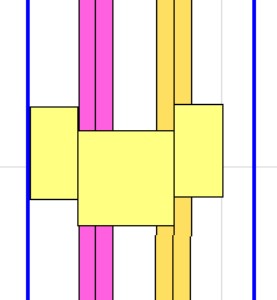
I did fiddle with the clearance on the left side a bit. I realized that when I said there were 3 tracks to contend with, I was inadvertently including the lower level track, Since it doesn't apply, we're left with the just dual mains.

The 1st photo shows how it is now. The yellow boxes are 3", 6" and 3" and the blue bench work lines are 14" wide. FWIW, the 3" from the wall is effectively 6" ctr-to-ctr track clearance. A clearance of 2.25" would equate to 4.5", the accepted standard for dual mains. However, we have to account for the curves on either end where 4.5" may not be enough for larger engines and that's why I use 3" from walls, etc.

Anyway, as you can see, the purple grade track is over 3" from the wall and less than 6" from the inside gold track. The 2nd photo shows how they'd look with the purple track moved over and the bench work narrowed to 12". Technically the gold track can be moved closer if I can account for the curves on the ends. The curve at the top is no problem because the 2 tracks diverge way before the end, so i just need to make sure the bottoms do too.
t

t2

Attachments

Images (2)
  • t
  • t2

Add Reply

Post
The Track Planning and Layout Design Forum is sponsored by

AN OGR FORUM CHARTER SPONSOR

OGR Publishing, Inc., 1310 Eastside Centre Ct, Ste 6, Mountain Home, AR 72653
800-980-OGRR (6477)
www.ogaugerr.com

×
×
×
×
Link copied to your clipboard.
×
×