Been a LONG time since I ran conventional on a regular basis (like 10 years or so) so I may need some refresh. 


Track is 0-27 style tubular track. I also use MTH Z-1000 transformers.


I'm running two basic ovals. One with 0-27 curves and two extra long straights in between. Got 2 power feeds going to it and it seems to be good to go. 


The larger loop is 0-42 curves with two extra long straights in between. As you can understand, nothing fancy. It has 4 power feeds going to it. I usually run this loop a good bit faster than the 0-27 loop. I've noted some speed fluctuation with the larger loop when ringing the bell and/or blowing the whistle. With a multimeter, I measured about a 2 volt jump when whistle and/or bell going. How much speed fluctuation is normal? I run MTH PS2 and PS3 engines and Lionel conventional. I've noticed some behave very differently. I have a PS2 diesel switcher and it really speeds up and slows down, sometimes substantially. No other engines respond this dramatically. An issue?


Could some engines just "adjust" differently to power fluctuations? Anything to worry about in terms of damage to engine, etc? Just "the way it is"? The smaller loop may respond similar but since I run quite slowly on it, it may just not be very noticeable. 

Last edited by SJC
Original Post

Replies sorted oldest to newest

Originally Posted by rogerpete:

I run the mth-1000 in conventional and do not notice any speed changed on my 3 ps-2 engines. However, my WbB and lionels will noticeably speed up. The whistle button may as well be labeled "Turbo Boost" on non-mth engines.

I've got 2 PS2s out for repair. Hopefully I'll get them back within the next few weeks. 


Available and in my basement, I've got 1 PS2 and 2 PS3s. I've noted that you will get some minor speed up with the PS3s. Nothing major but somewhat noticeable, especially when you hear the chuff on steam pick up a bit. 


The PS2 switcher, I've noticed REALLY does some speed up/slow down with the same train. I can say it is quite substantial. Blow the horn and sometimes it is running fine, other loops I'll blow the horn and it will substantially slow down. Slow down to a crawl, occasionally actually. I'm curious if there is really much to worry about and if some engines are more sensitive than others, etc. I've got the basic loop with 4 feeds which is sufficient I think. 

Last edited by SJC

Anyone have any input on that particular PS2 switcher? Like I said, it really has some speed variations. Blow the horn and it may speed up a good bit (normal). Blow the horn again and it may slow down, practically to a stop. It various speed/slow each time. I get some speed variation in other engines but this one is very substantial. Any input? No big deal? Big deal? Any negative impact on the electronics, etc. 

There seems to be many things to know about using a particular transformer with different engines. In my experience for example WBB Willaims does not run well on a Lionel CW80. The Atlas 0 (same as Williams transformer) does not run Lionel RTR Railsounds engines well either but run great on the CW80. When I was first started running MTH PS3 I believe it ran better on the Altas O then the CW80. I also added a the DCS system which run my PS3 locos on fixed and my Lionel RTR with Railsounds on variable. I also use a Lionel 1033 to run older stuff but just picked up a ZW last weekend and started to use it to run Marx and pre China Lionel and Willaims engines with it. If I ever get around to set up a standard gauge loop, I plan to use the ZW on that. I added a wooden base with old school style fuse blocks in pic below ...


ZW with base

Attachments

Images (1)
  • ZW with base
Last edited by yamawho

If you are running in conventional the same power reserve is not available for speed control.  So if a particular section of track has more voltage drop due to a bad connection, dirty track, the locomotive will respond and slow and speed up as it senses the voltage change on the track.


In command the voltage is always 18V even when going slow like the equivalent of 10V.  So even if you hit a bad section of track with voltage dropping to 13 or 14, the engine has reserve to compensate.


For the Switcher the issue can be dirty wheels and bad pickup rollers that drop the voltage.  I would inspect and clean the Switcher.  I would check for voltage drops on the track.   G

Last edited by GGG

Thanks G. Didn't think of "reserve voltage" in command vs. X volts you set in conventional. 


I assume there isn't much to worry about in terms of long term issues with engines?


I cleaned the wheels and rollers on the switcher and still found it to be a bit more "sensitive" to voltage variation. I guess it is just a bit more sensitive than the others. Regardless, I'd be curious to see how my two other PS2 engines perform when I get them back. 


Also had my multimeter hooked up to the terminal strip so I could monitor voltage and performance. I noted the engine seems to really jump or slow a bit when frequent whistle press is going on and the voltage is jumping a bit. Makes sense that would happen. Even though the Z-1000 only jumps the juice on the whistle by about 2 volts, lots of variation in a short time can get the engine to speed/slow. Also noted the bell drops voltage but don't see any slow down, maybe a bit of a speed up. Regardless, it seems to run well, just a bit more sensitive. 

Last edited by SJC

I have one section of track on my layout I need to fix.  I can tell as the engines go over it in conventional that there is a change.  Starts at a specific point and ends at another.  Track connections can get voltage drops at the connections after time. 


The other thing is to make sure the engine is well lubricated.  Some engine can be more sensitive than others, especially if the motors require a little more power to operate normally.  G

Thanks G. Granted this doesn't apply to non-speed control equipped locos but should I expect to see some speed up/slow down while whistling/bell ringing on speed control equipped locos? I know I don't have a voltage issue, it runs fine without whistle/bell. Do either or both w/b and we get some speed fluctuations. 


As mentioned, this one PS2 switcher has more noticeable speed fluctuations than my other PS locos. Only have PS3 now, my other PS2s are in for minor repairs. I'm curious to see how they perform.

SJC,

   A reminder for ya if you are going to use your old ZW's to run your DCS layout. Make sure you put Scoot type 10 resettable breakers between the TIU and your old ZW.  The ZW has old type slow blowing internal breakers which will allow your TIU to be damaged unless you use the 10 Amp breakers or fast blowing 10 Amp fuses.  


With your Z1000 your power should remain mostly constant, with maybe a little increase to the engines due to the DC off set, with the ZW as noted you will get a definite power boost when the control is pushed all the way up.  Not sure what happens with the P3 engines I do not own any, yet.


PCRR/Dave

Last edited by Pine Creek Railroad

Regardless of whether a conventional engine has speed control or not, it is still a variation in voltage that produces a change in speed.


Therefore, any transformer that supplies a voltage boost, whether it be the DC offset or the postwar 5 V boost, should produce a change in speed one way or the other unless the energy used by the whistle is exactly equal to the boost.


Jim


Thanks all for the input. Appreciate it greatly. Two things I KNOW are going on - 1) Having been YEARS since I regularly ran conventional, especially with PS2/PS3 engines, I need a partial refresh. Plus, I don't remember such things going on but then again, its been a long time. 2) I've been in a "fog" since tearing my old layout down about a year & a half ago, a major regret, and have had nothing but problems with pretty much everything I've set up SO, I'm pretty much convinced I'm having issues even when I may not be. 


Now.........


 1) I am NOT using a ZW or Postwar anything. All modern stuff. Z-1000 power supplies, Lionel conventional, LC+, MTH PS2/PS3 engines. 


2) Tubular track, 0-27 profile.


s


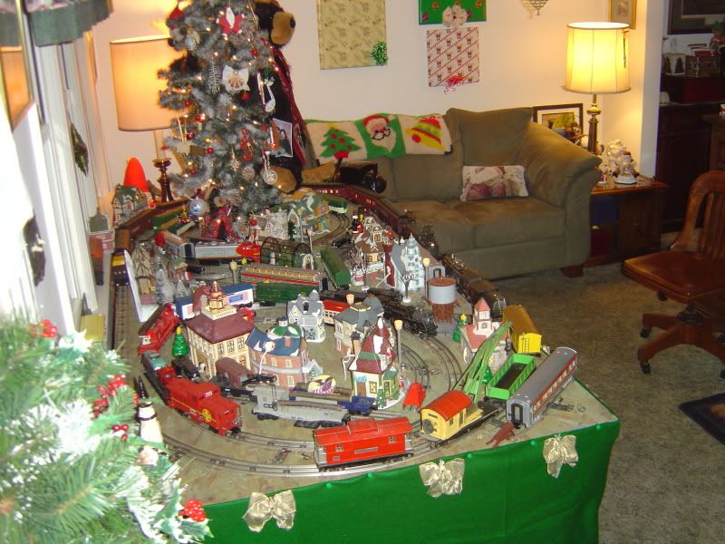
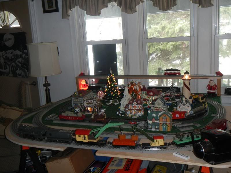
Here is a shot of what I'm currently working with. Inner loop is 0-27 curves with the 35" rigid straight on the right and a few standard sections on the left to accommodate the switch. Outer loop is 0-42 with two of the 35" rigid straights on each side. Pretty simple. (Ignore DCS set up). 


Inner loop runs fine with engines such as PS2/3 with cruise but I run that loop pretty slow, about 10-15 MPH if using DCS, estimated with conventional of course. Outer I run about 35 with DCS, estimated again with conventional.


Outer loop runs OK with cruise, nothing exciting until I blow the whistle, etc. Inner has two power feeds (18 gauge wire, not the best but the best I could get my hands on and work with). One feed right before the switch and the other by the caboose. Outer has 4 feeds. One right at transformer on left, one about 2 curve sections into the curve at the top, by the diesel sitting on the side, another near the 2 passenger cars and boxcar (right under middle passenger car) and the final right at the bottom right on the curve (visible in photo). All feeds are 5 track sections apart except the one in the bottom right which is 4 sections from the next behind the transformer. Again, 18 gauge wire. I think both loops have about as many feeds as they reasonably can handle and should have. 


Again, running cruise, etc in "standard mode" on the inner loop isn't an issue. Turning cruise off on inner found a lot of slow spots that I couldn't see with my sole non-cruise engine which runs at about Mach 2, even at the slowest transformer setting.


Outside, frequent whistle/bell presses can jump the speed a bit, such as the crossing (long-long-short-long) where voltage jumps around 2 volts at each button press. Particular on the right side, approximately from the boxcar at upper right to the curve at the lower right. Not every whistle/bell press results in speed adjustments. Only when done quickly. I assume, and please correct if wrong, the speed jump is caused the the frequent button pressing and the engine responding as a result to quick, approx. 2 volt changes? Turning the cruise off on PS3/2 engines, I found things to run a bit quicker in that section and SLIGHTLY slower around the rest of the loop  (and I mean slightly). I only have one non-cruise engine available, a simple Lionel RTR 4-4-2 but it's slow speed is more Nascar speed so it is hard to monitor but it responds the same - slightly quicker on right, slightly slower on left. I also think the speed adjustments are particular noticeable due to chuff speed rapidly increase or diesel roar increase then drop. Also can hear wheels on the track pick up speed. 


I'm generally concerned that this outer loop isn't really performing the way it should in the following ways:

1) Speed jumps, especially on right side while frequent whistle/bell presses. Seems to vary slightly in intensity depending on running slow (less juice) vs fast (more juice). Just "the way it is" with high/low voltage depending on operation?

2) One engine (PS2 SW1) seems more responsive to whistle/bell vs others (PS3 0-6-0 & Dash 8). My two other PS2 steamers are not available currently due to repairs unknown how they will perform (hopefully flawlessly!)

3) Concern over longterm operation with voltage variations, particularly with the MTH engines and $$$ electronics.  - bad? No Big deal? So far, seems like no big deal. 

4) My thought process is that any engine with speed control should not at all vary its speed regardless of whistle/bell or just rolling along. Perhaps I've been in command control with solid 18 volts too long....?

6) For example, lets say I'm running at 10 volts. Push the whistle, voltage jumps to approx. 11.2 - 11.5 volts. Release and immediately press again, voltage stops dropping and jumps back, sometimes hitting 12 or a bit higher. This is when the engines may start to jump a bit then fall back. Waiting about 2 seconds between button presses doesn't get this. I also tested in this way - get things running. Again, lets use 10 volts as an example. Push whistle, speed climbs to point A. Speed drops upon button release. Do not touch whistle, etc. Turn speed control dial on Z-1000 so voltage climbs to the point hit when whistle/bell press. Train runs substantially faster when voltage is turned up to that point vs when it reaches that point with whistle/bell. Normal?


Thats all I can think of at this point. I'm going to see if I can borrow a friends Williams GP9 to try out also and see how it runs, really just out of curiosity. Sorry for the long winded post. Haven't run trains like this, literally, in 10+ years. Been command control 100% of the time since. 

Last edited by SJC

GOt another question. On my basic oval, I've found that the trains speed up on the opposite side of the loop from the power feed. Running power feeds to the slow/fast spots don't change anything. Clearly that isn't right (should be faster near feed, slower away). 


I'm thinking of new track considering the tubular track has been pulled apart, pins pulled out, etc. perhaps the pins/connections just aren't very good despite crimping the connections a million times. Any input? New track an overreaction? Thinking about going Fastrack...

SJC,


Keeping your track in proper running order with tight connections is mandatory for constant powering, do some maintains on your track, make sure all pins and connects fit properly and clean your track, remove and replace any track that is not conducting power correctly.  Even new track can be faulty, especially today, the quality control is not what it use to be. 

I like FasTrack very much especially with the Command Control switches, I also have Atlas Industrial Rail, and an Inner loop of RealTrax along with Tubular in both O and 027, the last 2 tubular types now get used sparingly. No matter which track you happen to run, you still must maintain it properly.


PCRR/Dave

The 4x8 Conventional Tubular Christmas layout.


FasTrack with the new Command control Y switches


The Great thing about a DCS layout is that it can control conventional engines with the hand held remote control, I run my older Conventionals in this manner all the time.


Multi level FasTrack prior to the invention of Command Control Switches.

Last edited by Pine Creek Railroad

Under PS speed-control at, say, 30 sMPH (your outer loop), speed varies about 20 sMPH per Volt.  That is, changing track voltage by 1 Volt changes speed by 20 sMPH. 


So even a change of 0.1 Volt changes speed 2 sMPH.  While most people cannot eyeball such a change you can probably hear it thru the chuffing as you mentioned.  At 30 sMPH, a 2 sMPH change is about a 6% difference so the chuffing frequency changes by 6%.  That's about the same change of adjacent piano keys and I think most people can hear that difference.


So as others have suggested, carefully examine your track sections.  The engine can only sense the track voltage via the wheels/rollers so if there is a section of track where the pickups bounce (or whatever) and lose power, say, 6% of the time then the engine will slow down by about 2 sMPH.


If you turn speed-control OFF, there's another curious issue.  It is quite a hat-trick to design a transformer/controller that precisely inserts a DC whistle offset voltage without change the "effective" AC track voltage.  And of course it ideally does this over the full range of track voltage.  The effective voltage is that which gets applied to the engine's DC motor.  The AC voltage goes through a bridge rectifier and then has a capacitor which provides energy storage.  Depending on the type of AC controller (pure sine like the Z4000 vs. chopped sine like the Z1000) this capacitor changes the "effective" motor voltage and hence speed.


Bottom line is it's quite a complicated issue if you really want to get into the nuts and bolts.  In my opinion all this is no big deal. 


Thanks folks - appreciate the input. 


Stan - I assume you mean 2 sMPH vs 20....I think my trains would launch into orbit at that rate! 


I was able to secure a few "test pieces" of brand new 0-27 tubular track and put it in the original loop. I also noted the trains, with cruise enabled, sped up noticeable every time without fail. I think with all of the times the track has been taken apart, put together, etc the connections were poor everywhere except the new track. In addition, the 4 power feeds didn't seem to be able to overcome the poor connections. Still, the train shouldn't be slowing down near the transformer and speed up away despite having feeds in both locations. 


My plan, as of now - 1) Talk with my LHS tomorrow and get his input. 2) Replace the loop (outer loop), perhaps with tubular and NOT take it apart. Put it together and leave it together. That just works loose the pins and pinholes. I'll save the old stuff....it will give me a good excuse to do an elevated trolley type loop....!

Originally Posted by SJC:

Stan - I assume you mean 2 sMPH vs 20....I think my trains would launch into orbit at that rate! 


Not a typo.  20 sMPH per Volt when going 30 sMPH. 


In speed-control mode, the amount the speed changes per Volt increases with voltage.  It's like income tax...0 tax up to some level, then you pay some % on each additional $ up to the next bracket, then a greater % on each additional $ up to the next bracket. 


Back to PS speed-control.  Up to about 7V or so, you get 0 sMPH change for each Volt increase.  By the time you're going 30 sMPH, each Volt of change increases the speed by 20 sMPH.

Something else I just thought of, and it may not even apply in this situation, but...

I've used both chopped-wave (CW80 and Z1000) and pure-wave (Lionel KW, MRC Pure Power) transformers.  The pure-wave units produce a much more consistent speed around the layout than the chopped-wave units do.  With the CW and Z1000, the trains will fly down the straight sections and slow down VERY noticeably in the curves.  When using the KW or MRC, the curve slowdown is much less dramatic and speed is more even overall.  Wattage isn't really a factor, considering the KW would only have about 140 watts output for 2 trains.  With the others I had 80 and 100 watts for EACH track. 

Again, this might not apply to your situation as I have no locomotives with speed control, but it's a thought.

Thanks Stan & Mike. 


Got a new loop of track today. That seems to have (more or less) eliminated the non-cruise acceleration on the far end. 


Stan - that explains why my inner loop, which typically runs about 7-8 volts won't see any speed adjustments unless it is cranked up. I typically run the outer loop at about 10-12 volts which, visually, looks about 30-35. Didn't know that there was a certain threshold regarding speed up/no speed up. Good to know. Appreciate it. 


Mike - I get that as well with my non-speed control engines, particularly my steam engines. I see that caused by a combination of not enough juice to compensate for the drag. Plus, my 0-6-0 sees significant flange bind/drag in curves and it really has to be cranked up to get through it when cruise is turned off. 


Questions - I noted some engines are more "responsive" to whistle/bell voltage changes with cruise on. I also noted, with cruise turned off, engines still slow more, slightly, closest to the sole power feed on the loop and speed up, slightly, still on the far side. No change adding/subtracting feeds. Since the track is new, I don't suspect anything major (unless someone else thinks otherwise). The table probably isn't perfectly level and I suspect the indoor/outdoor carpet hides some imperfections when using a bubble level. I also noted that the train does not speed up on every whistle blast but will likely speed up when blowing the whistle in quick succession. I assume the voltage will jump even higher than usual but haven't tested to confirm. 

Last edited by SJC
Originally Posted by Adriatic:

Did the "bad" track have hollow pins. Keeping long term connections with those is iffy, and re-crimping well is a pain.  I prefer to replace them with solid pins as soon as an issue rears it head.


Hollow pins? Never heard of such a thing. I always assumed all pins were solid.  

SJC;

One other thing that can affect the train in a manner similar to yours.

My old layout was of level, Conventional Trains would always run faster toward the far end than coming back, direction of running on the track had some impact but not as much as the up / down hill difference of only a couple degrees.


So, If the new track has not eliminated the issue, Have you put a level on the track?

Yes there are hollow ones made in both blunt end, and "bullet point" style. I cant be 100% sure who's, or what year(s)(70s mpc?, re-pops?), but I do think it was Lionel. And, I have seen brand new tubular in a LHS, that had hollow pins in the last 5yrs. The hollow pins are plated & rolled steel, don't conduct well once even a little corroded/rusty, act like resistors, or even diodes, triggering whistles, and tend to get very hot, very fast. I've only seen them with the brown ties. Careful pin inspection will reveal a seam. Crushable with heavy pliers. Careful ordering by pins by price, watch for "solid" in descriptions.   

Russell - 


I must apologize for tossing your suggestion aside early on. 


I left only one feed, right at the transformer and ran trains "normally". Speed up on the far side, slow on the near side of the transformer. Tossed it in reverse....slow on the "far fast side" and quicker, or at least maintaining speed on the "slow close side." Adding a feed to the far side didn't change anything either. Shimmed up the table a bit and it is not perfect. May toss some more cardboard or another old kitchen tile under the legs. I used a level on the table and the bubble was slightly off-center but not really out of the level range. Appreciate the help. 

Add Reply

Post
×
×
×
×
Link copied to your clipboard.
×
×