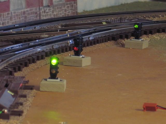
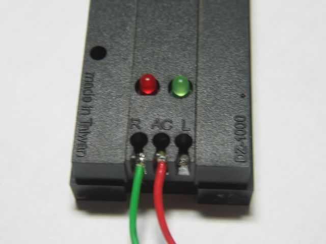
Picked up one of these since i liked the integrated Green/On and Red/Off LED in the toggle. It says it is for 12v DC (automotive use), so I was a little surprised that the LED worked just fine. Almost no voltage drop when wired inline with my track block (about 0.05v drop).

I am no electrical expert, but as I understand it the light is really only illuminating every other cycle, it just appears to be on because my eye cant detect the flicker. Any downside to powering a DC LED with AC track voltage like this? Shorter life? At $6 per I don't want to build a switch panel that burns out on me after a few months.

Original Post

Replies sorted oldest to newest

I take it that this switch has three terminals. +12, load, and earth. You are good with the half wave AC since the effective voltage is about 12.7 volts. But you should put a blocking diode in series with the LED to protect it from the reverse half wave. So put a 1N4003 from the earth terminal pointing to the ground instead of a wire.

Thanks for the quick response!

Yes, three terminals. I have attached screenshots of the switch package and an enlarged diagram. I am running

  • Common from my ZW to Terminal 3 (Ground).
  • ZW A voltage to Terminal 2 (ACC)
  • And from Terminal 1 (Power) to the track

This gives me track power and Green LED in the ON position, and Red LED but no power to track in the OFF position.

Not being well versed in electronics, I would have thought Ground and Earth are the same, so I am sort of guessing about how to implement your solution. Would I solder the diode pointing from Terminal 2 to Terminal 3?

Thank you

Attachments

Images (2)
  • Package
  • Large Diagram

In this case solder the diode to terminal 3 with the other end of the diode (the end with the line mark on it) soldered to ground. So you are connecting terminal 3 to ground thru the diode.
My auto switches called terminal 3 earth. But no matter, 3 is the negative terminal of the switch.

Last edited by cjack

Now that I know where to put the diode, I am thinking ahead to a switch panel with 20 of these. I could put a diode from terminal 3 toward ground on every switch, but could I just wire all the terminal 3s off of a daisy chain and have a single diode on the line as the wire leaves my switch panel to the ground?

Basically - yes. I prewired everything, including the diodes, about 1" apart and then drilled holes in the panel an inch apart and pushed the toggles up into the holes from below and secured them. I then added the leads and have had no issues - each toggle controls a siding.

If there is a schematic showing up, please disregard.


TOGGLE WIRINGTOGGLE WIRING TOGGLE 2

Attachments

Images (2)
  • TOGGLE WIRING
  • TOGGLE 2
Last edited by Richie C.
@S Rice posted:

Now that I know where to put the diode, I am thinking ahead to a switch panel with 20 of these. I could put a diode from terminal 3 toward ground on every switch, but could I just wire all the terminal 3s off of a daisy chain and have a single diode on the line as the wire leaves my switch panel to the ground?

Yes, just one diode on the line of terminals.

@S Rice posted:

While the LED flicker is not visible to me, and the brightness is ok, what kind of capacitor would I use if I wanted to smooth out the ripples? And I assume I would need 1 per toggle.

I don't see any way to do this with the way the switch is manufactured. If it were possible to separate the LED from the switch, you would also need to change the resistor value in the switch because the average voltage would be much higher.

Suppose you take the original track voltage and create a new voltage that is exactly 12V DC lower (more negative).  So when the track voltage is 0, the new voltage is -12V.  When the track voltage is at its peak positive, say +25V, then the new voltage is +13V.  When the track voltage is at its peak negative, say -25V, then the new voltage is -37V.

Then apply this new voltage to the "-" terminal of each switch.

Untitled

The Loads see the original AC track voltage when the matching switch is thrown - so no change there.  But the LEDs now see a steady 12V DC.

I'm throwing this out simply in the spirit of OGR being a discussion forum and not imagining anyone actually trying this!  Obviously the question is how to generate this "magic" voltage that is always exactly 12V lower?  This is somewhat akin to adding a fixed DC offset to the AC track voltage to activate bell or whistle if your conventional control train transformer doesn't have such buttons.  This is somewhat simpler because the power requirements are not as demanding - only a handful of LEDs rather than engine(s).

Attachments

Images (1)
  • Untitled

I am glad this question has been posted. I have a similar situation.   I want to send the transformer current to a section of track, using a Momentary on/off button switch.  In this regard, I have a question please which so far has not been addressed.

Can a 12 Volt DC battery switch handle the 16 volts, 8 Amps, 125+ watts of AC current that flow from the transformer to the track, without melting the switch?  Most of the automotive switches I see list very low amperage and only 12 volts DC. 

As the OP probably discovered, almost all of the really cool on/off switches with LEDs are made for use in cars for 12 Volts DC.   If you try to find them specifically for AC current up to 10 amps, they are really big and industrial looking.

Thanks for any info or ideas.

Mannyrock


@chuck - not surprised, and thank you for all the great information.

@stan2004 - pretty intriguing idea. I enjoy just playing around finding answers and may try that next year, but for now these DC switches will operate well enough with a diode. I’m under some time constraints to get up and running.

@Mannyrock - I actually took this toggle apart. The assembly that  “track” voltage flows through is pretty robust, good sized contacts that look more than capable (this is in the black body of the switch). The sensitive LED circuit is in the handle, and once I add the diode I think both the LED and the switch with track voltage should be fine last well.

i did play around with some push button style momentary and latch switches that didn’t look as robust.

Atlas had done a similar addition of LED's to their switch motors.  There was a small PC board, each dwarf light was triggered red/green from the switch motor direction.   

DZ 1000 switch motors have the LED's as part of the assembled unit.  The Red and Green LED may have to be reversed, for proper indication, note:  There is a flat side to the provided LED that is important.   

@Richie C. posted:


TOGGLE WIRING TOGGLE 2

I am an electronics idiot... but, I am learning (sort of).   It looks like I have the same toggles as Richie (mine are blue) for my yard as well.  They are hooked up other than the LED(s) as I had to wait for the diodes to arrive... which, I now have.  So, it seems that only one (1) diode is needed across the bus ground (earth) for this to work with all the LED(s) with the Stripe, facing the transformer ground.

Have I learned anything or am I still messed up?

Crap!  While I've got someones attention is the 1N4003 commonly used for passenger car led conversion... i.e., can I scratch that component off my list before I start that project?

The 1N4003 is a popular general purpose diode for applications up to 1 amp forward current and 200 volt reverse voltage. This means that you could protect approximately 50 LEDs in parallel with this in series diode.

Add Reply

Post

OGR Publishing, Inc., 1310 Eastside Centre Ct, Ste 6, Mountain Home, AR 72653
800-980-OGRR (6477)
www.ogaugerr.com

×
×
×
×
Link copied to your clipboard.
×
×