Hi Everyone,


Quick question, I have been debating adding an additional 180-watt Lionel Powerhouse to my layout.  


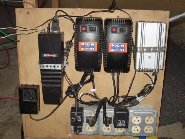
My current power setup is as follows:


Lionel 180-Watt Powerhouse

Lionel Legacy Powermaster

Lionel Legacy Base and Legacy Remote


Naturally, all of the wiring is pretty straightforward (I do not have blocks and/or power districts on my layout):


-Powerhouse to Legacy Powermaster via molex plug (Powermaster has ID: TR 2 in my Legacy system)

-Legacy Base Common to Powermaster Common (U to U)

-Hot and Common wires (A and U respectively) to my track from Powermaster


If I were to add an additional 180-watt Powerhouse, how exactly would I accomplish the inclusion of the additional brick?


Would I need to purchase an additional Legacy Powermaster, create the same aforementioned wiring set-up and then "phase" the Powermasters by connecting common to common on each?  Or is there a way to simply add the 180-watt brick using only one Legacy Powermaster? 


I appreciate the input.


Best,
Michael 


Original Post

Replies sorted oldest to newest

 
From the Legacy PowerMaster Operators Manual.  Looks like with an additional 180 watt power supply you wound need an additional PowerMaster.
Supplying power to your LEGACY PowerMaster

The LEGACY PowerMaster receives its power from an external power supply. It has been designed to operate with the Lionel 135W PowerHouse (6-12866) and the 180W PowerHouse (6-22983). It may also be used with any traditional transformer producng up to 20 VAC with a current rating of 7-10 amps. Use only traditional transformers that have a pure sine wave output such as the Lionel Postwar ZW, Lionel KW, MTH Z-4000, and similar transformers. Operation with transformers that have a chopped sine wave output such as the MTH Z-750, MTH Z-1000, MRC DualPower 027, Lionel CW-80 or similar transformers will result in unpredicable operation. To make the proper connections to a traditional transformer, you need a Power Adapter Cable (available separately, 6-12893).

TPC 400 (Track Power Controllers) could handle (2) parallel PH180's.  TPC 400s  were rated for 20 amps total capacity.  There was a connection adaptor  (6-14194) that connected the two PH 135's or PH180's to the input terminals of the TPC 400.

My experience with this power set-up using (2) PH135's was that specific blocks tapped off this initial power source had to be fused at no more that 7.5amps per block.   There is a lot of arc and spark welding available in this configuration on de-rails.
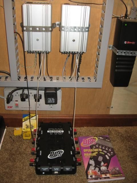
Note the modular "Y" connection, bottom of the silver box TPC 400 which allows the connection of the (2nd) Power house either PH135 or PH180.

More Power, Tim

Last edited by Mike CT

Johns not kidding about the welding. I guess the question is, do you really need the extra brick?


Are you popping the breaker on the one you have from overloading.


I initially had 2 bricks through a TPC unit because I thought I "needed" that much power for my 10'x16' layout. Any derailments resulted in spot weld marks on wheels and rail.


After John advising that it was " a ton of power", I disconnected one brick and discovered can run my trains just fine without it.  At the same time no "welding" during a derailment, I don't think there are even sparks.


FWIW I typically run 2 scale steamers with either 6 lighted passenger cars or about 15 freight cars and have a scale switcher working in the yard with smoke units on.


I've yet to pop the breaker on my 1 brick.


Getting power to the layout is also very important. I run 14 ga buss with 14 ga feeders every 10'. No voltage drops of any kind.

Originally Posted by RickO:

Johns not kidding about the welding. I guess the question is, do you really need the extra brick?


Are you popping the breaker on the one you have from overloading.


I initially had 2 bricks through a TPC unit because I thought I "needed" that much power for my 10'x16' layout. Any derailments resulted in spot weld marks on wheels and rail.


After John advising that it was " a ton of power", I disconnected one brick and discovered can run my trains just fine without it.  At the same time no "welding" during a derailment, I don't think there are even sparks.


FWIW I typically run 2 scale steamers with either 6 lighted passenger cars or about 15 freight cars and have a scale switcher working in the yard with smoke units on.


I've yet to pop the breaker on my 1 brick.


Getting power to the layout is also very important. I run 14 ga buss with 14 ga feeders every 10'. No voltage drops of any kind.

We, (The Fort Pitt Hi-Railers Pittsburgh, PA), use the two brick set-up for the Turntable/Roundhouse module.  When all the stub rails are filled, along with the (4) Roundhouse spurs, there is enough load on the circuit, that on initial start-up, the thermal cut out on (one) PH 180 will pop.  Up and running, and then you fill the display with engines there is no problem, your only operating two or three at one time. We added the second PH 180, as shown above.  We can power the module, loaded with engines, with no problem.  Again "More Power Tim" 

There are 14 stub-rails, some rails are long enough to handle (2) engines locomotives. The in-rush current , (14 or more units), on the TPC, turn power on, (TR #1/Aux1/Boost), is enough to trip the fast acting cut-out on the PH 180.

 Mike CT

Last edited by Mike CT

Michael,


I believe for most people the replies above are correct; 10 amps (one PH180 and one Legacy PowerMaster) per power district would be adequate.  However, my passenger trains are made up of multiple powered engines and 10 +/- lighted 18”/21” K-Line aluminum passenger cars with K-Line’s power hunger Streamlighting.  This needs quite a bit more power than what others run.  I’ve tried to run this train off one PH180 and the power draw from the engines and cars always tripped the PH180’s CB.  This was especially true when running my Legacy E7 ABA in this consist, where all three engines are powered.


As gunrunnerjohn said, there are always ways to solve this issue in a more elegant way.  However, keep in mind John may be a bit biased in his response


To solve my power problem I use two PH180s through a TPC400.  The TPC is made to handle more than 10 amps while a PowerMaster is not.  While the maximum output of my “transformer” this is 20 amps, I limit the amps to 15.4 by using an incredibly fast circuit breaker called a PSX-AC.  Here again I’m not sure how many people have even tried the PSX-AC, but there is just a minimal spark at the 15.4 amp setting.  There is much written on this CB here on the forum; if interested do a search for it.  Also, if you decide to add DCS with this much power, you will need to add the TIU in passive mode.


Before you start investing in this much power, make sure you really need it.  Even if you decide 10 amps is enough for your needs, I would still recommend adding PSX-ACs to your circuits.  It is faster than the already fast Legacy PowerMaster and PH180, plus it gives you some status lights and audio warning.

RickO, CAPPilot,


Appreciate the additional responses.  I surmise it is a bit overkill to try and install another 180-watt brick.  My 180 powers two main line loops and a few lighted accessories.  The other day, whilst running 5 Legacy diesels (3 with smoke units on), I noticed several of my incandescent bulbs began to flicker quite a bit, hence I became concerned about drawing too much amperage from my power source. 


In the interim, I solved this by converting several of my Lionel Yard Lights to LED illumination, as well as diverting several other lighted accessories to an old CW-80 I had lying around. 


I like to run large consists (4 to 6 engines), so was concerned as my layout and locomotive fleet expands, what is the proper way to handle the expansion in terms of power.   


Again guys, very much appreciate your responses. 


Best,

Michael

Michael,


John is correct that setting up power districts spreads the load, and there are several other topics that discuss them.  Power districts work well where you plan to run multiple trains on the same track, and each train needs less than 10 amps.


My question to you is how much power will a single train you plan to run going to need?  If you are running a single train that is pulling more than 10 amps, then power districts really won't help you.  For example, if you are running 6 powered engines (no dummies) that are pulling more than 10 amps total, then all these engines will be in the same power district at the same time and will trip the PH180 CB.


The only way I can see to run a train like you want is to put more amps to the track.  This can be done by paralleling PH180s or PH135s, with or without a TPC, or using any 18 volt AC transformer that puts out the needed amps (a TPC is only needed if you run conventional or want them for remote on/off capability).  As I mentioned above, if you do this you need real good circuit protection, and the PSX-AC will provide that.


So, if you think the number of engines you want to run in a consist will draw 10 amps or more, then you need to think about more power than one PH180 per loop/power district.  If you do decide to go for more power, here is how I set up my power with a TIU.  If you do not plan to use DCS, the choke is not needed.


TPC-PSX AC schematic

Attachments

Images (1)
  • TPC-PSX AC schematic

I would do insulted districts per track over the distance of say - a typical piece of straight track (about 1 foot distance per block) so that at no time is your average 6 axel diesel sitting on both trucks on the same insulated piece of track at the same time, nor is your average steam engine and tender with rollers (same goes for your lighted passenger sets). Then, if every other piece of track is being run off say 1 of 2 separate 180ph bricks - then you should have half the normal draw to each brick moving along the rails at all times. This can make a 15 amp train run without issues on a line that is only taking 7.5 amps from each of two bricks at a time while rolling from district to district, back and forth, every other piece of track. May be a pain to wire up your layout like that, but once it is built, it is built. As long as you keep each ofvthe two districts per track separate - you can choose to either wire each master cable out from track 1's district A and district B to two separate PH 180s - or plug districts A and B into the same power source together - at times when you do not need more than 10 amps - which essentially means, regardless of hardwired blocks and insulation, everything is running of the same source regardless. 

Thid method should avoid ever putting more that 10 amps into one piece of track, but in theory give you a maximum headroom of up 20 amp draw over a single train and no welding.

Im curious to know if anyone has ever successfully wired their tracks this way. 

This method works much like the idea of splitting data in half and striping it across lots of disks in a RAID 10 scenario, if you're familiar with computers. Just apply the striping to your track click wiring. The concept is similar.

rockstars1989 posted:

... I never heard of running two bricks to the same track. Lighting power is always a separate source.

The TPC 300 & 400 are devices that do exactly this.

TPC Connect

I have used two PM-1 controllers programmed to the same track number with two PH-1 bricks to power loops with long illuminated passenger trains. This method is not condoned by Lionel anywhere.

Attachments

Images (1)
  • TPC Connect
ADCX Rob posted:
rockstars1989 posted:

... I never heard of running two bricks to the same track. Lighting power is always a separate source.

The TPC 300 & 400 are devices that do exactly this.

TPC Connect

I have used two PM-1 controllers programmed to the same track number with two PH-1 bricks to power loops with long illuminated passenger trains. This method is not condoned by Lionel anywhere.

Rob I must be missing something is this installing two power bricks in parallel to increase capacity? If so then I would think power districts are a better idea. Maybe you can teach me more on this thanks Nick

Nick,

Power districts work well for a larger command layout where multiple trains are run on the same mainline track, and each train requires less than 10 amps. I believe a minimum of three power districts would be needed and one option would be each power district is powered by its own transformer brick.

My issue is I have one train that consistently popped the PH180's CB because it draws more than 10 amps.   It is pulled by an ABA consist were all three engines are powered with sound, and the train is made up of many incandescent lighted passenger cars.  Gunrunnerjohn may post he has a solution to this, but I think he is a bit bias

Anyway, on my old layout I solved the problem by using a TPC 400 powered by two PH180s.  My layout was wired per Barry's DCS Commandments (before his books) with pretty long blocks with no power drop that I noticed.  As will be pointed out by someone, the 20 amps to the track did make some sparks during a derailment although I never hurt any of those early TMCC engines.

Engine damage was a concern until I found salvation in an incredibly fast electronic circuit protection called PSX-AC.  Now any derailments had no sparks because the PSX-AC worked so fast.  I'm wiring my new layout with a Legacy 360w PowerMaster connected to two PH180s, and a PSX-AC to each track.  Lots of power, simpler wiring, and safe.  Downsides are the MTH TIU can't handle that many amps so it needs to be wired in passive mode, and a choke is needed to keep the PSX-AC from degrading the DCS signal.

2PH-PM-TIU-Track

Attachments

Images (1)
  • 2PH-PM-TIU-Track

For those interested, here is some more info on the PSX-AC.  Here is a picture of it

PSX-AC picture

Here is how I'm wiring it into my layout

PSX-AC wiring diagram

For the power-in and track power-on LEDs I use Miniatronics 12-030-18 bulbs, no resister.  The board in under the table, with the lighted switch and two LEDs available on a panel.

If a short occurs, the lighted switch lights up, the alarm sounds, and the track power-on LED goes out.  Once the short is corrected, press the lighted switch and the PSX-AC resets.  

As the diagram shows, the PSX-AC can be set for different max current amperages.  I have mine set at 15.4 amps, so that is the maximum that will get to the tracks.  The 12.2 amps setting probably would work, but the PSX-AC is so fast I'm not worried.


Attachments

Images (2)
  • PSX-AC picture
  • PSX-AC wiring diagram

Add Reply

Post
×
×
×
×
Link copied to your clipboard.
×
×