I decided it was time to post my question before I got too much father in my layout building.  I have an Atlas O72/54 switch on my layout and the dead spot is long enough that the new Lionel S-2 electric and an old Lionel 2-truck shay both die when they get to it.  To add to the fun, the O54 leg will go into the O72 leg of another one when I lay my inner loop this year.  Yes, I am using them as a crossover for my two loops. Not the best, but it fits, and I don't have a lot of room to use something else.).  Now it so happens I have a couple unopened Atlas 6924 boards, and remember reading they did power routing to help with kind of thing, but none of the links on Atlas's site for this board work anymore since they revamped it.  So my question is how do I wire the two switches and the boards to get power routing?  What modifications do I need to make to the switches so the rails won't short to the frog?  Can I do this with one board for both switches?  As this is a cross over, they'll always bee thrown together.  As for trowing the switches, it'll either be done manual or using LCS via my Cab-2.  I do not really want or need the non-derail function.  Will I still be able to hook up the Atlas dwarf signals to the board to if I can find any, or any other LEDs if I make my own signals?  Thanks.

(I tried searching for threads about this already, but I had no luck, except ones that pointed to Atlas's old links that don't work anymore.)

Original Post

Replies sorted oldest to newest

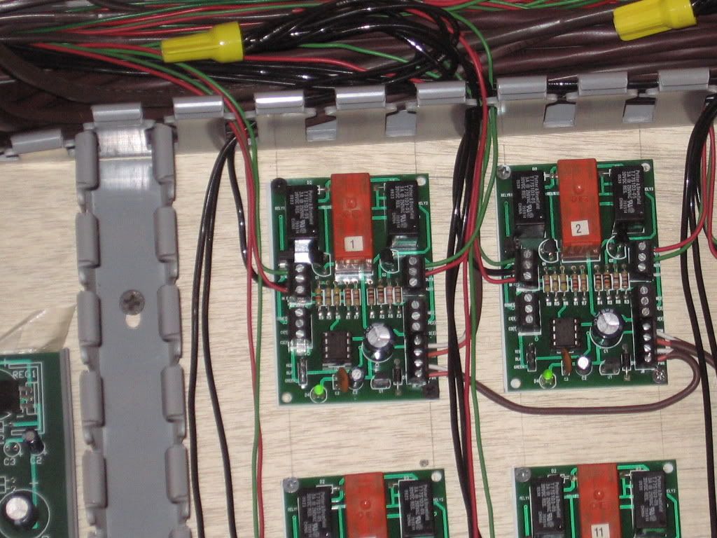
Reference to the 6924 relay board.

Partially wired board.

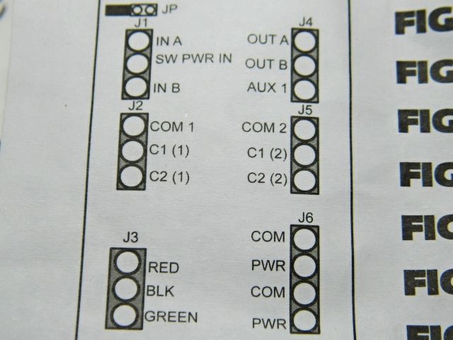
COM/PWR, COM/PWR.  6 to 22 VAC/DC is the 6924 Circuit board power.  The two sets of terminals allows for daisy chain wiring of more than one board.  Powered, a green light should show at the bottom of the board.  

In A would be from your push button (momentary) (Atlas #56 or, the more elaborate #57 pushbutton), either through or out.  (switching commons/outside rail).

In B the other push button (momentary) (#56 or the later more elaborate #57 pushbutton), either through or out.  (switching commons/outside rail).

SW PWR IN  Accessory power used for the switch motor. (Power/ should be in phase with the center rail).

Out A   Power to the Atlas switch motor, (momentary).  The 6924 has a time out feature, to inhibit switch motor burn out.   SW PWR IN provides power to Out A.

Out B  Power to the Atlas switch motor, (momentary).  The 6924 has a time out feature, to inhibit switch motor burn out SW PWR IN  provides power to Out B.

Common to switch motor.  Not provided through the 6924 switch board.  

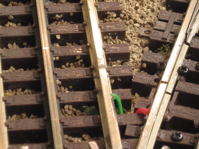
Non-derail wiring.  At or near the  switch frog, two isolated out side rail sections need to be wired as an additional input  In A and In B.  A wheel axle combination will automatically power the switch motor through the 6924 board to move the switch points.  Note the green and red wires attached/soldered to the small sections of rail at the frog.

The green and Red wires pictured connect to INA and INB on the board, in addition to the pushbuttons.


Power Routing.   Using the J5 terminals.

COM2  Track power from the switch into the 6924 switch board.

C1 (2)   Track power from the 6924 board to the one of the dead rail sections of the switch.

C2 (2)  Track power from the 6924 board to the other dead rail section of the switch.

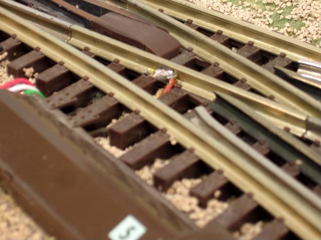
Wiring to one of the dead rail sections. Red wire/solder center of picture.   Power is logically supplied to this track section via the 6924 board. Green wire is attached to the other/curved dead rail section pictured.   I found that fusing with a 3 amp fuse worked well. Power routing is not a refined art.  Moving axles and wheels tend to be temperamental at times. 

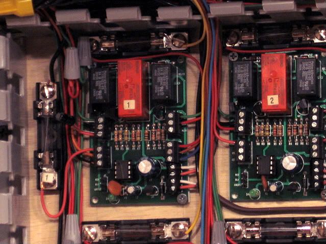
Board wiring with the Power routing fuse(s) top and left.

Note that  COM1, C1(1), C2(1) Relay is designed to be used with terminals J3 to power 6931 dwarf light signals

I have used the  COM1, C1(1), C2(1) Relay  for additional power routing of cross over switch (Pairs) but the JP1 jumper must be removed.  One 6924 relay board will work a cross-over pair of switches and do the necessary power routing.

A short tutorial on the Atlas 6924 relay boards.

Best wishes with your project.

Mike CT.


Last edited by Mike CT
sinclair posted:

I decided it was time to post my question before I got too much father in my layout building.  I have an Atlas O72/54 switch on my layout and the dead spot is long enough that the new Lionel S-2 electric and an old Lionel 2-truck shay both die when they get to it.  To add to the fun, the O54 leg will go into the O72 leg of another one when I lay my inner loop this year.  Yes, I am using them as a crossover for my two loops. Not the best, but it fits, and I don't have a lot of room to use something else.). Used as a crossover one 6924 board will work both switches.   Now it so happens I have a couple unopened Atlas 6924 boards, and remember reading they did power routing to help with kind of thing, but none of the links on Atlas's site for this board work anymore since they revamped it.  So my question is how do I wire the two switches and the boards to get power routing? Detail in this thread, non-derail is a must, part of the logic of powering dead rail sections of the switch  What modifications do I need to make to the switches so the rails won't short to the frog? Usually the rails are isolated with air gaps. I used small pieces of styrene strips, some locations.  Can I do this with one board for both switches?  As this is a cross over, they'll always bee thrown together. Again, one board will do both switches. If two different track circuits are involved, Power routing will require the second relay and the removal of the JP-1 jumper.   As for throwing the switches, it'll either be done manual, manual will not work, the logic of the board is electric via the relays. or using LCS via my Cab-2.  I do not really want or need the non-derail function. non-derail is part of the installation, a must do.     Will I still be able to hook up the Atlas dwarf signals to the board to if I can find any, or any other LEDs if I make my own signals? Eventually I hooked the 6931 dwarf lights to the switch motors  with the small relay board provided with the dwarf lights, there is a wiring diagram.  As a cross over pair, more than likely, you will use both relays, on the 6924 board, for power routing, unless you are using one track circuit for both tracks, involved in the cross over.   Thanks.

(I tried searching for threads about this already, but I had no luck, except ones that pointed to Atlas's old links that don't work anymore.) Apparently nothing last for every including you and me.     Best wishes with your project. Mike CT. 
 

Last edited by Mike CT

Add Reply

Post
×
×
×
×
Link copied to your clipboard.
×
×