Good Evening Group.
Is the stock speaker in these units the best available for this locomotive or does anyone have a better option?
Thanks,
Stephen Wilson
|


|
Good Evening Group.
Is the stock speaker in these units the best available for this locomotive or does anyone have a better option?
Thanks,
Stephen Wilson
Replies sorted oldest to newest
certainly not the best option. the OEM speaker is thin due to height restriction. you can do better with a QSI, Soundtraxx or TDS speaker. the trick is to find one that fits.
Small. 8 ohm ?? .1 watt. Three Rail.
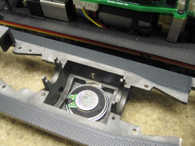
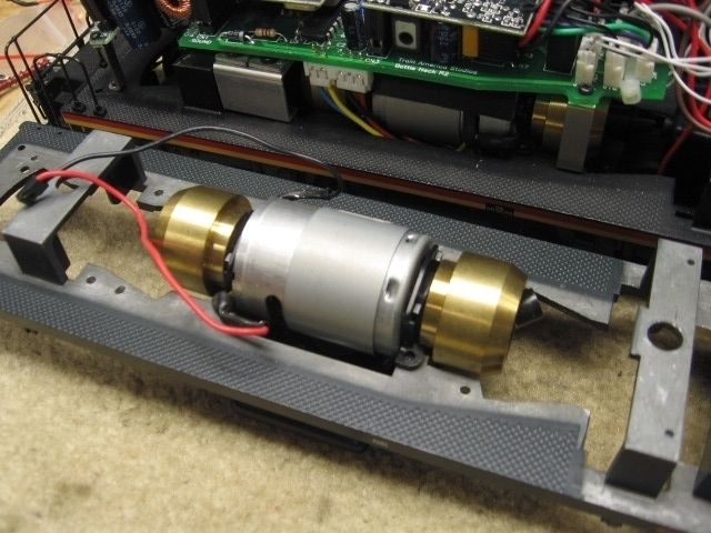
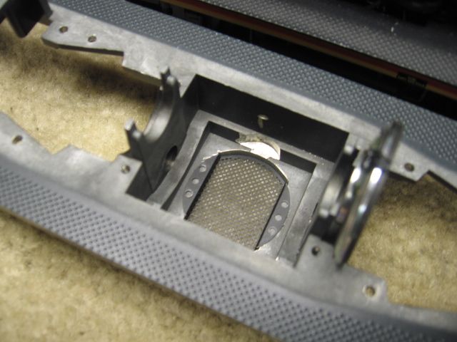
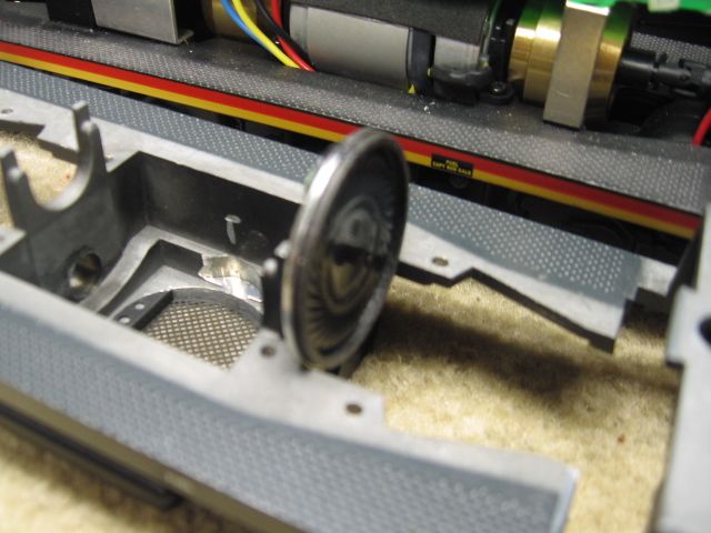
Some of the first issue Atlas SW9's (1999) had the speaker mounted in the front hood area, This Dallee Sound system was poor at best. Above pictures are a conversion of one of those 1999 SW's to TMCC and sound.
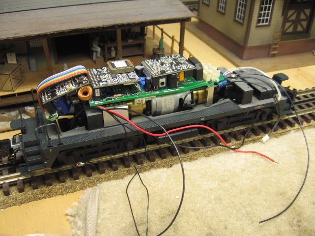
Note the see through hood exhaust grill where the speaker was with the Dallee system.
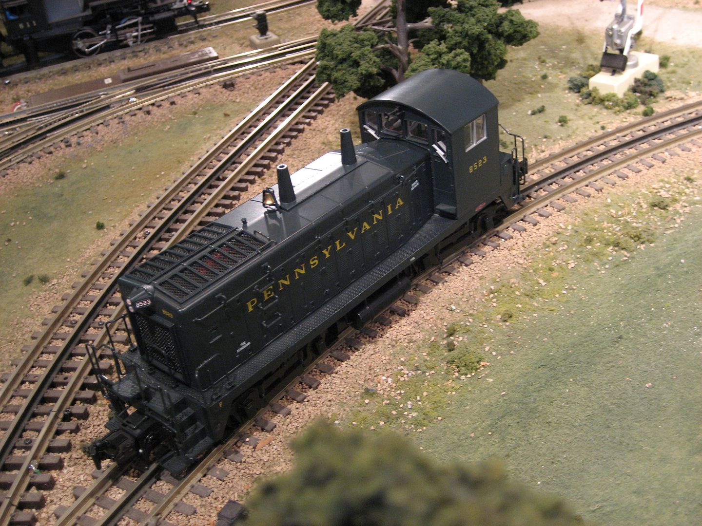
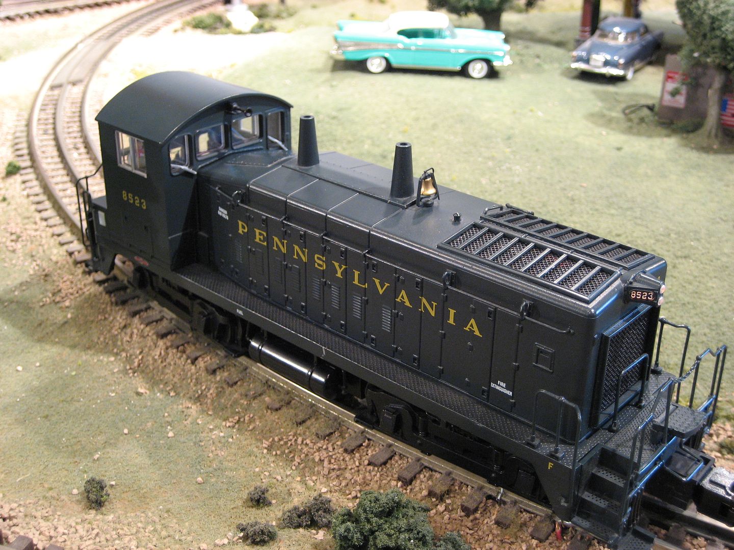
Best wishes with your project. ![]() Mike CT.
Mike CT.
IMO Best sound is multiple units/multiple speakers.
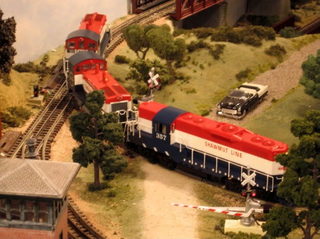
A picture of the original Dallee drive board and speaker that was hood mounted.

I understand that the following won't work for everyone. There is another option that produces a significantly deeper bass response if you are willing to do a little work and:
In 2-R there is just enough room inside the hood for new electronics. First remove the lighting board if it came without sound, or gut the electronics otherwise.

Build a styrene platform that stretches across the tops of the gear tower mounts. You will need an extra M3 screw for this. After this photo was taken I added another layer of styrene at the front to recess the screw head. A full-length platform keeps the wires away from the flywheels.

There is plenty of room to locate the decoder and a Tang Band T0-2008S speaker module. Cut off both mounting tabs from the speaker and attach it with double-stick tape. The following photo was taken after I cut off only the front tab. Later I removed the rear one so that there would be room between the speaker and decoder for a Loksound PowerPack. The speaker and decoder are held down with double-stick tape.

The 4 ohm TB 2008 has a round speaker and an oval passive radiator, which are the keys to the module's greatly-extended bass response. The small red circuit board manages wires and will make it easier to disassemble in the future. Also I have not yet connected any lighting wires.
Here's what it looks like with the shell on.

The decoder received ESU's Full Throttle 12 cylinder EMD 567 sound file. It sounds great, but default volume was way too loud and also drove the speaker too hard, producing distortion.
Eventually I plan to strip the thick paint, re-detail for a more prototypical appearance, then decorate it for the A&O. Part of this will involve opening the rectangular radiator area for a scratch built radiator assembly and that will allow sound to more freely escape. The core will be dark green silk to model the appearance of weathered copper and allow sound to escape. Here's a small photo of an SW1200 I reworked many years ago that sports a new radiator. It will eventually receive an ESU-TB upgrade. The stock SW8 on the left will eventually receive the same treatment, but with an 8 cylinder EMD 567 sound file (ESU has a the recording, but has not yet released it.)

Perhaps this will be of some help, or at least spark an idea or two.
I used this one from Railmaster Hobbies.

Comes with its own enclosure. Not a Fatboy but much better than the OEM Atlas speaker.
Pete
Has anyone measured the full depth between the fuel tank and the motor? Is that thin speaker the biggest that will fit?
I have 3 or 4 of these engines laying around waiting for either TMCC signal installed or a PS3 upgrade.
Drift here, but I'm going to try the same install as Bob shows, but in an Atlas mp15dc converted to sw1500. Except I'm planning on getting a Tang Band 1931 in there with the Loksound, come h*** or high water. Lot's of filing to be done yet. I need about another 1/16" clearance.
Jim
Jim -
Wishing you the best of luck with the 1931. If you succeed the sound should be best-in-class. Are you absolutely certain that there is enough vertical clearance between the bottom of your reworked hood and the front truck mount for a 1931, including headroom for speaker cone excursion?
Please don't try substituting an HO Loksound decoder just because it is much smaller. I thought about going that route, until ESU confirmed that others have tried and decoders were fried.
By the way, in the A&O forums there are a few frequency response curves measured by a friend for the smaller 1925 module and some other alternatives, including two Railmaster bass-reflex modules and a cell phone speaker. The 1925 has a bit deeper bass response and can handle more power than the 2008. It is my go-to speaker for hood-unit diesel installs.
All the best, Jim!
riogrande491 posted:.....Are you absolutely certain that there is enough vertical clearance between the bottom of your reworked hood and the front truck mount for a 1931, including headroom for speaker cone excursion?
I thought I was. But now you've made me paranoid. I'll have to double check. I am planning on using the Loksound L for O scale.
Maybe I'll move this discussion over to the A&O forum. I signed up recently but haven't posted yet, after your discussion with Mario about these speakers.
Jim
Btw, if anybody goes looking for the specs for Tang Band speaker modules on the Parts Express website, it seems likely that the specs for the 1931S module are incorrect. They appear to be the same as for the 1925S module, copied and pasted. At least for frequency response and dimensions. If you go one layer deeper by clicking on the pdf link for specifications at the top of the page, you will see that the 1931S is in fact larger, and has a slightly broader response spectrum than the 1925S.
Jim
riogrande491 posted:Jim -
Wishing you the best of luck with the 1931. If you succeed the sound should be best-in-class. Are you absolutely certain that there is enough vertical clearance between the bottom of your reworked hood and the front truck mount for a 1931, including headroom for speaker cone excursion?
Please don't try substituting an HO Loksound decoder just because it is much smaller. I thought about going that route, until ESU confirmed that others have tried and decoders were fried.
By the way, in the A&O forums there are a few frequency response curves measured by a friend for the smaller 1925 module and some other alternatives, including two Railmaster bass-reflex modules and a cell phone speaker. The 1925 has a bit deeper bass response and can handle more power than the 2008. It is my go-to speaker for hood-unit diesel installs.
All the best, Jim!
Bob, your work on the SW is outstanding all around, and thanks for the sound research on A&O forum!
FWIW I was able to fit the 1925 in using your platform idea and a TCS WOW HO Diesel decoder with KA2. I did put a brass plate heat-sink under the decoder just in case. I have had no issues with overloading pulling 20 x 1lb cars on level track.
Jim: To me the 1925 sounds nicer than the 1931 even though the 1931 goes a bit lower. I think it might be because the 1925 is rated at 1W as opposed to the 1931 at 4W. I have a 1931 in an F Unit but I find transients, bell and horn seem more punchy/real with the 1925. Also I placed the driver right under the bell and the passive radiator towards the exhaust which I drilled out more. Helps me to believe the bell is making the sound. ![]()
Again FWIW I have 2 MP15DCs with Loksound Select HO decoders and the same 1925 setup and have no overload issues with them pulling 25 x 1lb cars on level track. Although they do run as a pair which no doubt helps. I love that 1925 - heck, I even shoehorned one into my Yoder 44 Tonner. Don't ask... ![]()
my install is similar to Bob's. I built the styrene platform and used a NCE 13SR decoder for control and an older DSX for sound. Not the most up-to-date pairing, but it works fine. I did open up the radiator grill for more air and used a 1.25" speaker in a square enclosure. Not as much bass response as a Tang but I lowered the volume, it sounds great.
sorry no pix. I usually neglect to photograph my work.
I also have installed LokSound HO decoders in my Atlas SW9's and MP15DC. Nothing fried. I will have to look but I think I used a stock Atlas speaker in the SW9. I cannot remember if I relied on the body to be the enclosure or if I sealed the speaker area with styrene.
Loksound, like all brands of sound decoders, are set way too high. I adjust the overall volume down to about a setting of 80 which is about 60 percent of the max volume.
Bob, I always loved your work on the A&O and David Stewart's kind answers to my correspondence (before he moved into that new house) went a long way toward getting me into 2R.
Last fall I installed one of Soundtraxx's new Tsunami2 2 amp decoders in my AtlasO SW9 switcher. One of the smoothest out of the box locomotives I ever owned became even smoother running. Their EMD 567 sound set is improved and I like the auto notching, load sensing effects over earlier Tsunami's. I've found Soundtraxx's tech support to be top notch - in no minor part due to the design and manufacturing to be here in the US. Unfortunately there has been a several month delay in production of the 4 amp Tsunami2. Meanwhile I've installed 2 amp TSU2200's in four other O scale locomotives that had current draws within the capacity of the decoder.
Along that line, and following a recommendation from master modeler Jim EuDaly , I'm going to replace the Pittman 9334 motor in a heavy Overland PRR M1b with a coreless Maxon. Jim totally re-motored his large C&O roster (see Feb 2017 RMC) of O scale locomotives with smaller high efficiency coreless motors, enabling him to use HO sound decoders. A second order benefit was that the decoder along with most of the wiring stays in the boiler along with the speaker. Smaller coreless motors enabled Jim to dual power his articulateds. With a motor and decoder for each engine the chuff now comes naturally in and out of sync - something I may try in a PRR T1 duplex someday.
Keystoned Ed posted:.....Jim totally re-motored his large C&O roster (see Feb 2017 RMC) of O scale locomotives with smaller high efficiency coreless motors, enabling him to use HO sound decoders. A second order benefit was that the decoder along with most of the wiring stays in the boiler along with the speaker. Smaller coreless motors enabled Jim to dual power his articulateds. With a motor and decoder for each engine the chuff now comes naturally in and out of sync - something I may try in a PRR T1 duplex someday.
this sounds interesting. Lionel tried one engine with the speaker in the boiler and I never heard of any more. It would seem better to use the tender for sub woofers only.
So now to find out about coreless motors.
......any suggestions about a speaker?
Thanks,
Stephen
Maxon seems good as Engineer Joe says. See a possible source here:
https://ogrforum.com/t...10#70974704590210010
I do believe he has supplied some large O scale layout owners. Not sure if the one mentioned above.
Stephen: For speakers see posts above re Tang Band 2008, 1925, possibly 1931.
Back to speakers, here is a quick iPhone audio recording of a TB 2008 driven by a Loksound L decoder, playing a correct 12 cylinder 567 sound file. Although the still photo shows the shell off the engine, the audio was recorded with the shell on. Those who have installed a TB 1925 will get a bit deeper bass.
The iPhone microphone is set up for voice, not music, so it isn't the most accurate.
Hi Bob. Thank you for the photo and the sound file. Very nice. As this is my first install of DCC and sound into a locomotive (the SW8) would you mind providing the following:
a) What gauge of wire did you use speaker to decoder and motor to decoder?
b) To the right of the decoder in your photo is a connector board, I would like to hear more about that....materials, where to obtain them. It appears it was used rather than hard wiring the motor and pickups to the decoder?
Thanks in advance,
Stephen
WOW! The installs with the locksound decoders sound great!
https://bobsobol.smugmug.com/T...n-an-RS-36/i-kKpjXJT
Stephen -
I'm not sure of the wire AWG from the speaker. That wire came pre-soldered to the TB 2008 speaker. The wire runs are so short, and current so small, that pretty much any gauge wire that you like to use would work. On their HO decoders, ESU Loksound seems to use 36 AWG. In other installs I've used 32 AWG because I have a couple spools of that. Bigger wire won't help but won't hurt either, except to make it a bit harder to wrestle everything into place.
I had to lengthen the Atlas motor and pickup wires, so I used 26 AWG stranded that I had on hand. Atlas states that the motor stall current is 3A or less, so pretty much any wire gage down to 28 or even 30 AWG could be used, again because the runs are so short.
There is no reason that one can't just solder all the wires directly to the decoder. I chose to add a small board to make disassembly easier in the future. Small diameter wires are pretty easy to solder, remove, then re-solder. But sometimes the individual strands in larger diameter wire seem to go wild during unsoldering, making it necessary to cut off the end and get a fresh insulation strip. Do that several times and the wire suddenly grows too short.
The speaker, decoder and little red board are held in place with Loctite clear plastic double-stick tape from Ace Hardware. I find it has a tenacious grip but doesn't leave a foam residue behind when removed.
The little red prototyping board is from Sparkfun. It is pre-scored to make it easy to snap it into smaller pieces. It is a bit pricy, about $8/sheet but it is enough for many installs. It also has plated-through holes, so the screw terminal connectors have a stronger mount. Link to red prototyping board
The green screw-terminal connectors are from Mouser. Prices fluctuate, currently $0.52 each. Link to green terminal
The green terminal block on the engineer's side provides two convenient places to connect right rail pickup wires. Underneath the board is a single wire, soldered to both pins, which then connects to the decoder's R track solder pad. Likewise for the green block on the fireman's side, and the left rail pickups.
The block at the rear connects the two motor leads to the decoder. Before putting the shell back on I test the locomotive to see if it runs backwards. If so, it is a simple matter to swap the two motor wires.
Please note that one should never tin a wire before inserting it into this style of terminal block. Over time the solder compresses and the connection becomes loose.
There is a black TVS or Transient Voltage Suppression diode on the red board, just barely visible. I wire these directly across the track pickups because the A&O is a huge layout and many of the DCC bus wires are very long. With a full CTC signal system, we can't install resistor-capacitor "snubbers" across the DCC bus feeds under the layout, as they would trip occupancy detectors. For a normal DCC system set to 14.5V (HO), this part from Mouser is: Link to TVS diode
For normal size O-scale layouts this diode is probably not needed.
In this particular install, I directly-soldered the headlight and rear light wires to the decoder. Eventually I will strip the paint, re-detail, and paint for A&O. At that time the bulbs will be replaced with LEDs.
I hope this answers your questions. All the best.
Bob. Thank you for taking the time and effort to respond so thoroughly. Greatly appreciated.
Stephen
Stephen - You are most welcome. Glad to help, if only a little bit.
Today a better microphone for my iPhone arrived in the mail. Unfortunately the SW9 is 25 miles away on the A&O but I did have a decoder set up on the test bench, connected to a slightly-larger Tang Band 1925S module. This speaker fits in most brass hood units.
The sound file is for a 2000 HP 12-cylinder Alco 251. It is a 4-stroke engine that is naturally throatier than a 567. The increase in bass is partly due to the quality of the recording, partly the better microphone, and partly the larger speaker. But it is representative of what we are able to get on the A&O with Loksound and Tang Band speakers.
The following is a near-field recording, with the microphone about 3 inches away from the speaker module.
Darned sweet recording. Although I kept looking for Alco smoke and to see some movement on a track. Hard to believe all that sound was coming from some electronics and a little speaker. LOL
Dan
So looking for some opinions here. I have two Atlas locomotives, an SW8 (no electronics except headlights) and an Atlas SW9 with all the electronics (DCC). The SW8 has the open louvers on the top of the chassis so it will get a Tang Band speaker and Loksound Select L Decoder. The question is, since I am going to upgrade the SW9 from the stock QSI Decoder to a Loksound Decoder should I remove the speaker from the fuel tank and open up the louvers on the top of the chassis for a Tang Band speaker or just upgrade the stock fuel tank speaker?
Thanks,
Stephen
Stephen -
I haven't investigated better speakers for the SW. I'm sure Pete's speaker would sound better. In 2007 I installed one of the OEM Atlas fuel tank speakers and a Soundtraxx DSX in an SW1200 (NCE ATLO decoder for the motor.) It sounded great at the time, but now I'm spoiled.
How comfortable are you with opening the radiator area? It isn't a small amount of work but can be accomplished with hand tools. If you keep the stock Atlas grill then the hole won't need to be especially neat because it won't be visible. On the SW1200 I opened the oval cutout using a Sherline mill then filed the corners square. This was done so I could add a scratch-built, visible radiator core. I left an 0.030" lip all around for mounting K&S aluminum screen on which a styrene frames were built in-place. Soon that engine will get a new radiator core that is acoustically-transparent and a TB+ESU kit.
All the best.
I would vote for the full upgrade on the second unit. If you are careful with the removal of the QSI electronics, you could probably sell them here or via ebay to recoup some of the cost of the new parts.
Plus I would take the opportunity to correct the detailing on the radiator section a la the A&O engine that Bob shows.....the bars should be under the screen, not over it. You can also add some depth in the process.
Jim
To clarify (since we can't edit our own posts) I haven't investigated better fuel-tank speakers for the SWs.
If you care to upgrade the radiator, as Jim suggests, a prototype radiator cores sit 7" below the screen wire. So do the support bars. There were 3 individual cores on each side, with pairs of dividers that stand proud of the cores. I have a few close-up photos.
riogrande491 posted:.....(since we can't edit our own posts)....
Hmmm, the first option under the "Take Action" button at the bottom right of my post says "Edit".
Thanks! It was right there all along! ![]()
Stephen -
You could even go a little bit crazy with scratch building new details... ![]()

Following what I've learned in this thread, I just bought a pair of TB speakers to install in an up-detailed USH GP7 - my first O scale diesel purchased new in 1971 for $125! The body detail isn't as fine as the best of today's plasticgeeps but its brass body and chassis is solidly built. I totally rebuilt the drive train with a Pittman gear head motor and gearboxes now offered by Jay Criswell and Protocraft. My best runner, closely followed by the Atlas SW.
It currently has a QSI Titan in it driving a single 8 ohm 1.22" QSI hi bass speaker. The decoder has stero ports so if space allows I may go with two TB's. If I replace the speaker with a 4 ohm TB's am I correct in understanding that all I need to do is add a 4 amp resistor in series with each speaker?
Hi, Ed—
It was a pleasure and honor meeting you a year ago at the A&O.
For a single TB speaker and a decoder rated for 8 ohms, a 4 ohm resistor (you can probably cheat a bit) should keep the decoder happy.
For two TB speakers, if they fit, you could wire them in series to get 8 ohms. However, if I understand correctly the QSI decoder can be configured to play different sounds through each speaker amplifier and if that's what you want, go with 4 ohm resistors.
If my options were to go with a pair of smaller 2008s or a single 1925, I'd go with a single 1925. Leave perhaps 3 to 5mm of clearance above the speaker for cone excursion. These modules like to hop! If placed on a desktop, they will skitter all over the place.
Very nice! I'm drooling...
Bob
Thanks for all the responses. I am comfortable "performing surgery" on the SW9 so as to mount the speaker on the top below the grills. Better to do it now rather than redo the process in a year. On this unit the area where the radiator goes is solid, recessed slightly from the remainder of the roof, but forms part of the shell (i.e. cannot be readily removed). As a "quick" short term fix I see Atlas sells replacement grills, not sure what the actual part number(s) or name(s) of parts required as there is only one partially labelled parts diagram on the web?. The other option is to cut the blank out of the shell and replace with a scratch built grill/radiator.
Thanks again to all who have responded,
Stephen
Good Evening Bob.
If you have time to respond....I have been trying to source the four pin connector (male and female) you have used connecting the motor leads from the decoder to the PCB board........I can't seem to find a mating pair at Mouser, Digikey, Semtec etc.
Thanks,
Stephen
Stephen-
The SW9 doesn't have a 4 pin connector. Are you thinking of a different install I did in a Car & Locomotive Shop RS11 shown on the A&O web site, or an RS-36 install on my Smugmug photo sharing site?
Maybe this board from an RS-36? Is this the droid you're looking for?

The 4 pin connector in this photo is usually sold in long strips. It can be chopped into shorter lengths with a hobby knife. The mating connector is the same part. On the bottom it has round pins that perfectly fit in the female side shown here.
I'm not sure where I got this gold-plated one but they are available from a wide variety of vendors. Here's a link to a tin-plated 20 pin strip at Mouser. Link to Mouser catalog for Mill-Max connector
To make the mating connector assembly, hold the connector in a small vise such as one for a drill press or metal jaws of a Panavise. Clamp the round pins as a heat sink. Fill each cup with solder. Strip the wire very short, no more than 1/16" long and tin it. Heat the cup and insert the wire into the cup. In the photo below of an RS-36 shell, I made a mating connector using 26 AWG stranded wire.

Before anyone wonders why I'm using a Loksound HO decoder here, Henry Bultmann told me that he specified custom Pittman motors for his C&LS diesels. He stated that they were 24 volts, but on a 12 volt regulated lab power supply the 8414-size motor only draws 1.1 A with with the armature locked. A regular 24 volt motor would stall around 4 to 5 A. So I'm not sure what motor he used, but the stall current is just right for an HO decoder.
All the best.
Access to this requires an OGR Forum Supporting Membership
