Intelligent CB
PSX manual
Never have to worry about buying fuses or blown up electronics.
|


|
Replies sorted oldest to newest
quote:Originally posted by Charlesp34:
Sam, do you have one installed on your layout? If so, can you answer some of the questions I posted earlier. Thank you.

quote:Originally posted by Pine Creek Railroad:
SW1,
Gary I have three sets of them, purchased from Scotts years ago, they get the job done.
Each of my old ZW & KW transformers has a set of them covering all the different track on my
FasTrack layout.
PCRR/Dave
I discovered what I believe is an error in the PSX instructions (or maybe this information will be old news).
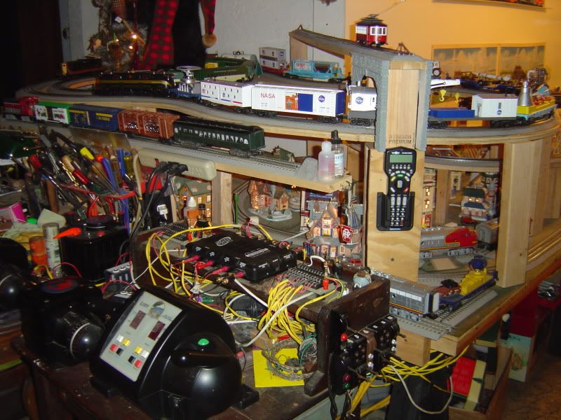
I added a set of reset buttons, and then discovered when testing nothing seemed to work right. Studying the board copper traces, reading the instruction sheets (gasp!), and sluething with an ohmmeter showed J1-3 is a straight through dead short common to J2-1. J1-4 to J2-2 has very high resistance as it should with the triac and other parts in series from J1-4 to J2-2.
Since most layouts use outside rail as ground/common and isolated center hot rail for the blocks/power districts, the breaker(s) if wired as shown in the instructions, appears to be measuring the common outside rail current(s) rather than just center rail current. If using several breakers as I do, weird things ocurred as breakers interacted with ground loop currents from other districts.
My remedy was to put the transformer common ground to J1-3 and then ran J2-1 to my outside rails. I put my transformer hot lead to J1-4 and then ran J2-2 to my center rails of each block/power district (in other words, I simple reversed all J1 and J2 leads.) Now each breaker promptly trips without affecting the others and resets as it should.
As an aside, I used J1-1 and J1-2 to power the AUX input to the DCS TIU box so TIU stays alive rather than resetting, so other trains will not go out of control because TIU is dead (the TIU will re-send a watchdog signal when it senses channel voltage has returned.) Polarity matters as the AUX connector outside barrel is common to the TIU black binding posts and TIU electronics is not isolated from track hot and common. Thus, J1-1 is common to J1-3 that is defined as transformer common. Of course if you are using a stand alone transformer/wall wart supply, this this paragraph does not apply.
Access to this requires an OGR Forum Supporting Membership
