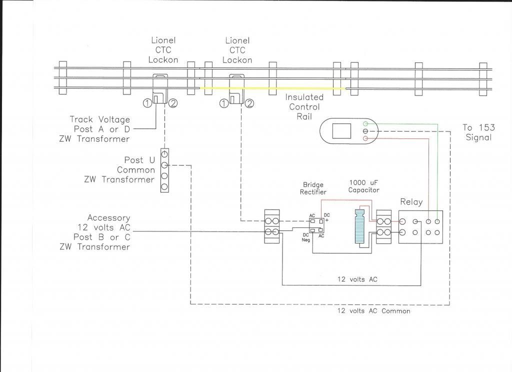
How does one do it? Interested in installing bi-directional block signaling on this single track main between two reversing loops, a classic dog bone. Is there a circuit diagram available or a detection board that is necessary to make this happen? I have a fist full of relays and the track is Gargraves so insulated sections are easy. Just need some guidance how to logic it out. 
I also just found out that Christopher is out of business so that resource is gone.  

Thanks in advance!

Original Post

Replies sorted oldest to newest

Jim -

How long is your single track mainline between loops?  Long enough to hold more than 2 trains? Long enough for 2-3 signal blocks?   You want to prevent a train from one loop to enter the single track and cause a head on crash.   And you can set up to allow a second train to follow a first train through the single track.  There was a post not too long ago about the use of relays.  Here is a copy of a simple relay circuit that I had posted on that discussion about relays.  I show just one signal.  By adding relays and signals you can have multiple signal blocks. So at a boundary between blocks one could have 2 signals - one facing East - one facing West.   And you can have 2 signals on one relay for each signal block, one at each end of the block.


Right click on the image and select view image to get a larger picture

hope this helps

Steve


Last edited by Steve24944

Logically speaking, if you're just using two-aspect signals -- red/green or red/4-second yellow/green -- then simply placing signals at the ends of the block tied to the same trigger circuit is sufficient. If you're talking about three-aspect -- true red/yellow/green -- then it gets a little more complicated as you need to adjust for the yellow aspect from both directions.


Which types of signals are you working with?

For three-aspect signaling, you need to divide the railroad into at least four blocks.  Two signals are required at each location for opposing signals. (The signal with two heads at the lower right corner of the photo governs the adjacent track.  The opposing searchlight signals adjacent to the front of the tender are called a fixed pair.


IMG_2056

Attachments

Images (1)
  • IMG_2056
Last edited by Number 90

In real life, railroad Signaling is not like traffic lights where they are based on a timer and expect traffic to respond to it.  Instead, the Signal should indicate the state of the track block(s) behind it.


Signaling can get complicated very quickly, I think the simplest approach is to look at an ABS System  (Automatic Block Signaling)  example.  Assuming you have three aspects on your signal (for example red, yellow or green), If the green aspect is seen when approaching signal from the engineers perspective, the next two track blocks (track circuits) after the signal should be clear (no train occupancy).  If the yellow aspect is displayed only a single block behind the signal is clear.  Is the red aspect is displayed the next track block is not clear  

Where one signal governs different direction than the other signal, but both are at the same location, if circuit before and after the location are occupied at the same time (such as when the train passes by the Signals), both Signals should be red.


I think a quick search on google for "three aspect railroad signaling" might have some good visual images.  Maybe try this link from which I took the following image: http://www.railway-technical.com/US-sig.shtml


Last edited by Hump Yard Mike
Originally Posted by Jim Battaglia:

... How does the relay sense direction and fire the correct signal? (east bound or west bound) There is a logic sequence I'm missing. 

Mike's diagram is perfect for the discussion.  Assume the 2 ends are loops as in your dog bone.  I suppose you could create "logic" that detects direction of travel.  But it seems easier to assume the straight section is clear to start.  Then the first train that enters the straight determines whether the straight is operating Eastbound or Westbound.  That would set a circuit (relay) that tells each signal whether it should be looking "left" or "right" to determine aspect.


If you're trying to implement the logic only with relays, I suppose that could be done since you can cobble together the basic logic functions (AND, OR, NOT) with relays.  But it would be a mess of wiring and consume a lots of power.  I'd think someone sells a board that does this and I'd continue looking.  But if you like soldering and don't mind messing with small components, I'd think all the digital logic chips to implement the signaling for the diagram shown (6 each direction, or 12 total 3-aspect heads) would be, say, $10.  And you could save the relays to switch power to the blocks for automatic operation.

Mike's diagram is an excellent illustration of how ABS works. You can replicate the three-aspect operation using pairs of DPDT relays (one for each direction) in each block. I'm digging up the schematic for one I was considering putting in at the club a few years back (too expensive and time consuming to implement). The operation of the layout I used would not be true ABS as the signals surrounding the occupied block would cascade from red to yellow to green as the got farther out from the occupied block, where the ABS system sets everything to red ahead of the approaching train. But it would look nice seeing them change.


Z-stuff signals, using their infrared sensors, can be wired to operate like an ABS system with minimal invasive wiring on the layout by connecting the yellow wire from a signal to the white wire of the one ahead. This causes the signal to hold on yellow until the next signal is cleared. What I don't like about the system is that because it's optical, there's no way to cover the whole block -- just where the train passes the signal.

Add Reply

Post

OGR Publishing, Inc., 1310 Eastside Centre Ct, Ste 6, Mountain Home, AR 72653
800-980-OGRR (6477)
www.ogaugerr.com

×
×
×
×
Link copied to your clipboard.
×
×