So I'm wondering if there is cheap way to detect over-current? (or any particular current)


To make a very long story short:  I found these awesome panel meters below with relays that allow an over-current to be set and trigger something.  After about 20 emails, it turns out they are $600-$1500.  They are from Watanabe Electronics if anyone wants to know.


I'd like an indicator pilot light or buzzer that turns on a little before our breakers trip.  The idea is that the kids (and myself) would get a little warning if we approach the maximum breaker hold current rather than everything just going off or running just above hold current for a long while.  I think this way I'll be able to keep my breakers rated really close to what we need.  Ideally, I'll be able to combine this with some of the LED indicator circuitry I've seen on the forum that indicates when a breaker has actually tripped.  The main thing is my son and I are just learning about electronics and the more fun stuff we do with it the better.


I was thinking that perhaps a current sensing relay could be used but I'm still looking at $30-$200 per circuit it seems.  Then I was wondering if perhaps a PTC fuse rated just below our breaker hold current to throw a NC relay might be possible but I can't figure out how it would be in-line (in series) with everything and not stop all power to the track when it trips.  Not sure using a PTC as a switch is a good idea either.  That's about as far as I can get.  At this point I just need a push in the right direction to see if detecting over-current is feasible and to know what haystack I should be looking in.  Thanks.

Original Post

Replies sorted oldest to newest

These may be close to what you want.


http://www.dccspecialties.com/...s/pdf/man_psx-ac.pdf


http://amhobby.com/products/te...owershield_x_ac.html


And you can buy them here too...


http://tonystrains.com/product...ent-circuit-breaker/


The description does say they can differentiate between a direct short and just over current when using an excess of lighted cars, etc. I'm not sure what remedy they employ in the case of smooth over current...need to read more on them.

These electronic breakers are the fastest that I have found though, preventing arcing for the most part.

Last edited by cjack

Thanks Chuck.  I sent them an email.  I had seen those PSX-ACs before in other post and was planning to go to them, and replace our breakers with them in a year or so.  Didn't notice they made that differentiation.  However for the price I might could find a over-current relay but then if I'm going to PSX-ACs in the end it might be better just to make that jump now.


Not to be too picky but I was trying to hold off on PCBs and ICs for as long as possible just so it's not so abstract and something that doesn't start looking like magic to my son.  Though, not sure that matters.  He is really getting circuits, switches, relays, breakers, fuses, diodes, and resisters, but that's about it.

Wow! Talk about a interesting subject. After all my years in the hobby I am face to face with another, very expensive "toy". I can understand the basics. What I cannot understand is,"Why?". In years past we built our layouts to handle so much and always knew those limits. As an example, on one of my last prewar layouts I had five std gauge loops. I used two Lionel Z Type transformers. These ran vintage prewar trains plus prewar accessories. The limits of power were never exceeded. If I'm missing something in the translation, please, explain in everyday, easy to understand English.  

Pappy,  There are folks running 3 engine Lashups with dual pulmore motors so 6 AC motors; with 4 of these running at a time. So occasionally 2 6 motor engines wind up on the same block.  I have seen layouts with 4 Power Houses in parallel feeding one block.  So 40 amps available. 


So times change and some folks push limits that Command Layouts allow.


A Z-4000 will indicate an overload and flash a red warning beyond the meter displayed amps.


I think a good reasonably priced amp meter works.  G

Nice video!


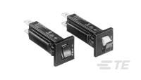
Guys I was trying to be brief so I probably wasn't clear.  I was more thinking about our small breakers, not the transformer breakers.  We are using these currently for bus lines:

I know you experts know all about these from other post in the forum.  I went with them over PTC for the main bus lines so the kids would have a visual indication when a breaker trips and so the power would not come back on until reset. 


These TE breakers, at say 135% of breaker current load the tripping time will be 1 hour. 


The idea is that if we approach or slightly go over our TE circuit breaker limit (or PTC fuse limit in some cases) then we would get a warning and back off a little. Then the breakers are not sitting there getting hot for an hour before they trip, or 10 minutes, or any length of time.


So that's the WHY.  Does that make sense are am I just being stupid?


Also we are running a ZW on a pretty small 11'x12' layout so will probably not ever push the ZW unless there is a major short.  


Not holding us up from getting wired up by any means but just thought it would be fun to do and show my son how warnings can be built into electronics when ranges are exceeded.  Fun except for the price that is.  I know you see RPM and under-over voltage warnings things like that in industry all the time on dangerous equipment.  However, I'm finding that to teach my son something better than I learned it is not easy for some reason.  If only those panel meters were $30 we would be using them.


Also, if anyone is interested in those panel meters then email me and I'll share some of the more detailed emails with a number of specific product numbers and the American distributer.

Originally Posted by rtr12:

Happy Pappy,

Here's an example of what GGG was talking about with some folks pushing the limits.

rtr12,

Wow!!..OK  It's basically doing the same thing I did years ago? I always had a certain level of power in reserve. The video is a good example of something I find confusing. I'm sorry, it happens a lot these days. But, Thank you!

Originally Posted by willhi895:

Nice video!


These TE breakers, at say 135% of breaker current load the tripping time will be 1 hour. 


The idea is that if we approach or slightly go over our TE circuit breaker limit (or PTC fuse limit in some cases) then we would get a warning and back off a little. Then the breakers are not sitting there getting hot for an hour before they trip, or 10 minutes, or any length of time.


So that's the WHY.  Does that make sense are am I just being stupid?


Also we are running a ZW on a pretty small 11'x12' layout so will probably not ever push the ZW unless there is a major short.  


Not holding us up from getting wired up by any means but just thought it would be fun to do and show my son how warnings can be built into electronics when ranges are exceeded.  Fun except for the price that is.  I know you see RPM and under-over voltage warnings things like that in industry all the time on dangerous equipment.  However, I'm finding that to teach my son something better than I learned it is not easy for some reason.  If only those panel meters were $30 we would be using them.


Thanks, Tommy Z definitely knows how to run trains!


The 1 hour at 135% is what steered me away from the TE breakers. Some folks on here swear by them so I got some to test (I think I got a different brand, but same specs, will have to check on what I have?) and they actually tripped a lot faster than that with a short on the track. These breakers are fine for postwar trains. Newer trains with modern electronics maybe not so much, at least not for me. I don't want to risk a $500 engine with a $5-$10 breaker when I can have a much better electronic breaker for $50 that has spike protection as well. If you have a postwar ZW and modern engines, get the PSX-AC's that cjack referenced above. They are electronic and have spike protection as well. I use them myself with the PH-180's for power. I have command control only, all modern electronic engines.


The Lionel PowerHouse-180's that GRJ mentions also have excellent breakers and are very fast acting. Similar in reaction time to the PSX-AC's. If you have a ZW-L then you already have excellent breakers and protection for your trains. You could still add the PSX-ACs, but I am not sure that would really be needed? That's another subject for the electronic folks to comment on. That's above my level of electronic know how.


You can also get some cheap volt and amp meters on ebay to monitor your power usage. Like the ones you referenced in your first post, only the economy version. These can be purchase from the Asian suppliers on ebay for prices starting at around $6-$7 for analog and about $6-$20 or so for digital and ammeter with shunt. I would recommend the analog ones for just monitoring, the digital ones are a little more complicated to wire up. They require an isolated power supply. GRJ assisted me with my second round with the digital meters. Don't ask what happened to the first set.  If you are interested I can post some links for some of these.


Originally Posted by Happy Pappy:
Originally Posted by rtr12:

Happy Pappy,

Here's an example of what GGG was talking about with some folks pushing the limits.

rtr12,

Wow!!..OK  It's basically doing the same thing I did years ago? I always had a certain level of power in reserve. The video is a good example of something I find confusing. I'm sorry, it happens a lot these days. But, Thank you!

You're welcome, glad you liked it. I think he said he was putting 30 amps to the track on that video. Don't remember if this video was one of them, but he has overloaded some of the equipment pretty bad a time or two. He has some more really neat videos like that one on his youtube channel. He also has an extremely nice layout, at least I would love to have one like it, but I am not sure I would have the nerve to try some of the things he does wit his trains. He has a LOT of nice trains too. He is also a forum member here and still posts occasionally. You may know him?


His youtube channel was one I found when I was thinking about getting back into the hobby. Needless to say I was impressed and it affected my decision as I am now back in for the long haul. There were others as well, ericstrains youtube channel was another, as was the command control systems, MTH, Lionel, Atlas and others.

Originally Posted by gunrunnerjohn:

Here's another "pushing the limits" with long trains.  This is two locomotives and 115 cars, and I managed to do it with 10A maximum on each power district.  The run included a 2% grade around 30 feet long at one point, all the curves were O72 or larger.


Not even close to a limit....  12 to 18 Pulmore motors on a block with 40 amps provided.  Now that is a limit!  G

So far this looks like it might be the cheapest way to get the current detection I'm hoping for.

CR9621 Adjustable Current Switch ($44.15)


I can't seem to find the range of adjustment for the set point but I have an email out to them.

(Edit: It comes in 3 ranges.  The exact product number for the 1-10 amp range is CR9621-10-ACA to switch AC voltage. )


That's still on the high side so I'm not sure I'll do it if it cost that much.


What I really need is something cheap like a TVS for current, where electricity, over a certain current, is allowed to pass through to a another circuit.  Maybe that's not possible.


I do have lots of regular panel meters.  Still trying to decide what size to use but I have a few to choose from.  Attached are my round ones.  I'm hoping to run for a year or so with simple engines and electronics, then next year move to the more sophisticated stuff.  This is as much a electronics project for my son as it is a train project so I don't want to skip over the basics.  Plus, blessed kid, he's only 11 and doesn't need everything at  once.


We're off to a simple start but thanks to you great folks here at OGR I think our start is solid.


Attachments

Images (4)
  • IMG_2412b
  • IMG_2413b
  • IMG_2414b
  • IMG_2415b
Last edited by willhi895
Originally Posted by willhi895:

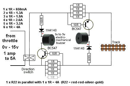
Well, here's a possible circuit.  I just got this from TalkingElectronics.com.  Nice folks.  I will need some sleep before I digest it.


Here is the link to that circuit on they're "75 Model Railway Projects" page.

http://www.talkingelectronics....ts.html#Over-Current


This circuit is going to give you an audible alert to an over current problem but it won't do anything about the problem. Before you have a chance to react, damage can be done to your modern trains. As an electrical engineer I would buy the electronic circuit breakers earlier in this thread. The electronic circuit breakers have the ability to react on the microsecond to millisecond time scale and stop a short circuit while the current is still rising toward its peak level. Regular circuit breakers react more slowly due to being thermal devices and can allow much higher currents and take on the order of seconds to trip (time to trip would depend on the circuit breaker selected and the current during the short). I'm sure some of the more experienced engineers could fill you in more...


Are you really sure your problem is drawing too much current from say too many lighted passenger cars vs. plain dead short? I might be running 1:1000 or so on how often. That is to say, you spend all that money and time, and find out stupid shorts are your problem?


This website has lots of geeky stuff, including imported-from-China panel meters, including watt meters with A, V, W and trip points ....


http://www.lightobject.com/Default.aspx


The objective here is to get an alert if the system gets within an amp or two of reaching breaker levels, regardless of what breakers are used.  I was just trying to figure out what is the cheapest way to accomplish what those panel meters at the top do to see if I want to do this.  If there is a short or something, then the breakers will obviously need to do there job and shut everything down.


As for doing the same thing with the PCX-ACs.  Larry at the Train Exchange tells me that you can do this with 2 PCX-ACs.  On the one closest to the ZW, mount the sonalert and set the current trip to 5 amperes. You will then need to SHORT OUT Q3 and Q4 so they can't turn off the current. Connect the input of the second PSX-AC to the output of the first and set it to 9 amperes. At 5 amperes, the sonalert will sound on the first PSX, and at 9 amperes the second PSX will open the circuit.

You are still leaving 3-4 amps on the table with the PSX-AC's. I wonder if you could do something similar with the less expensive TE breakers in a smaller range? Something to think about. That would be a lot cheaper, if it would work. I didn't really think it through, just had the idea from your post above about the PSX's.


Veris Industries is another source of current switches. They also have current sensors that might possibly be used with an Arduino or similar control device. The industry I was in before retirement used them a lot. They have some that are quite sensitive, some with built in relays and other options. I looked a few up on the internet and they are similar in price to the CR9621 you posted above. My former employer got much better pricing, but they were a large company, used a ton of them and purchased directly from Veris.


Originally Posted by rtr12:

I wonder if you could do something similar with the less expensive TE breakers in a smaller range?

This might be a start of an idea or something really dangerous.


Breaker Circuit2

Breaker A would act as a trip and reset.  Would be cheap and the range could be whatever you want by changing breakers A and B.  Not sure if it would work in the real world.  If you really had a serious over-current, "A" would have to trip, then "B".  Two surges may hit the track.  The best I can do with my feeble mind.


The TalkingElectronics circuit seems a lot more elegant.  I modified the image, as I understand it.  I think the circuit was probably with 2 rail in mind.  For 3 rail I think we only need half the diagram and I added a breaker, like Matt said, for actual protection.


Breaker Circuit3


Attachments

Images (2)
  • Breaker Circuit2
  • Breaker Circuit3

Add Reply

Post
×
×
×
×
Link copied to your clipboard.
×
×