After reading many posts on our forum and watching an assortment of Youtube videos I'm still confused on the use of Atlas snap relays when wiring switch machines.  If someone could answer these basic questions I sure will appreciate it:

I want to use Atlas #57 switch controls for my turnouts - I know I can wire them directly to the switch machine but I've heard that an Atlas snap relay #200 can be used also.  

Question #1:  Do I need both components (#57 & #200) or do I use one without the other?

Question #2:  What is the purpose/function of the #200 snap relay?  (What does it do that enhances the operation of the turnout?)

Question #3:  What is the function of an Atlas Non Derailing Circuit Board (#6924)?

Question #4:  Do I need an Atlas Non Derailing Circuit Board if I use a snap relay?


I know these are very basic questions but I need someone to explain to me the "best" way to wire my turnouts so that I don't fry the switch motors.  A simple diagram would be very helpful and appreciated.


Much Thanx,

Paul

Original Post

Replies sorted oldest to newest

From the Atlas website.  200 Snap relay would be wired parallel with the switch motor.
Requires a common, Through and Out from the #57 or #56 push buttons. As noted it allows several functions related to enhanced switch operation.  Note that most of the detail explanation is related to HO switching.  

A double-pole, double-throw relay with actuating mechanism driven by a momentary-power, twin coil solenoid. (A solenoid is a cylindrical coil of insulated wire in which an iron core is made to move back and forth by a flow of electric current.) With just a few simple connections, this small device, which may be mounted anywhere, can:

  • Power the frogs on Atlas' Mark 3 & Code 83 #6 turnouts
  • Control trackside signal lamps to show turnout point positions
  • Operate control panel lamps to show settings of remotely located turnouts (switches)
  • Provide selective track siding control. Sidings are powered only when points are aligned for siding. Siding remains dead when points are set for the mainline.
  • Control X-sections automatically. This very useful track arrangement is thoroughly discussed in Atlas' Complete Wiring Book.

#57 lighted switch control is a relatively new push button switch control that has lighted through and out indications.  Not required, you can use the switch button provided with the Atlas track turnout switches.  I believe it is listed as a #56 switch control, through and out.  Noted problem with the #56 is stuck buttons that causes the switch motor burn outs. I don't know that using the #57 lighted switch control would solve the burn-out problem, contact Atlas on this.


6924 relay board. has a built in time-out feature that inhibits switch motor burnout. It can be used with your existing #56 push buttons.  Push and hold the button too long the relay board will time-out preventing switch motor burn out.  The #200 snap relay would not time-out.  Good chance that a stuck #56 button will cause both the switch motor and the #200 snap relay to burn-out at the same time. The 6924 board will also address the dead spot problems of the switches and there are other functions.

There is a lot of information on this Atlas page about the 6924 relay board.

(1.) One of the problems with the Atlas spring loaded non-derail switches is they don't seem to work well.  If you enter a switch the wrong way the spring loaded points are to give enough that the train will roll though the switch without de-railing.  First function of the 6924 Non-derail board automatic switching when you enter a switch from either direction.

Non-derail wiring diagram.

(2.) Established automatic non-derail allows for power routing of the dead rails in the center of the switch.  Doing this should enhance engine movement through the switch assuring power. Power routing.

Power routing.

(3.) You can also add the 6931 dwarf lights if you wish using the 6924 relay board. I preferred to use the small PC board provided with the dwarf lights.

6931 Dwarf lights added.

(4.) Using the #57 switch with the 6924 relay board. Note that the red/green indicators on (#57) are powered through one set of contacts on the 6924 board. There are (2) sets of NC/C/NO contacts available on this board.

#57 button/6924 relay board. 


Question #1:  Do I need both components (#57 & #200) or do I use one without the other?  If you are using the #57 switch, the #200 relay is used to power the LED/red/green on the #57 switch. This diagram.  

The #200 relay would also allow for electrical enhancement of the gap/dead spot in the switch, or the addition of some on-layout switch indication lights. There are (2) sets of normally open (NO), common(C), normally closed(NC) contacts.

Question #2:  What is the purpose/function of the #200 snap relay?  (What does it do that enhances the operation of the turnout?) Note the power routing diagram, provided via link above.  The #200 relay would provide the ability to do power routing, which eliminates the dead spots in the center of the switch.  It also powers the red and green LED's on the #57 switch.  

Question #3:  What is the function of an Atlas Non Derailing Circuit Board (#6924)? Noted above.  Primary function is to inhibit switch motor burnout. There are other functions available.

Question #4:  Do I need an Atlas Non Derailing Circuit Board if I use a snap relay? No, but the snap relay would not solve the problem of switch motor burn out.


Hopefully that get you started with these interesting devices.

Best wishes Mike.

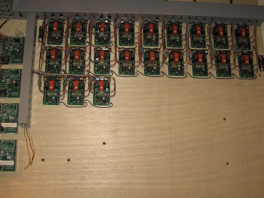
A couple of my 6924 relay boards installed.

 I haven't burn a switch motor since I installed the 6924 boards.


Last edited by Mike CT

Mike CT, I have a Atlas O #57 switch machine on my layout wired directly to my Atlas O switch and I don't have a Atlas O #200 snap relay wired to it. All I done was replace the original switch box (black switch box with lite blue button) that comes with the Atlas O switches with the new Atlas O #57 switch box. On my yard and crossover switches, I do have Atlas O #200 snap relays wired in only to wire my MTH signals to. That way I'll know the direction my switches is set in............rogerw.


Originally Posted by ROGERW:

Mike CT, I have a Atlas O #57 switch machine on my layout wired directly to my Atlas O switch and I don't have a Atlas O #200 snap relay wired to it. All I done was replace the original switch box (black switch box with lite blue button) that comes with the Atlas O switches with the new Atlas O #57 switch box. On my yard and crossover switches, I do have Atlas O #200 snap relays wired in only to wire my MTH signals to. That way I'll know the direction my switches is set in............rogerw.


Wired per this diagram  The red and green LED's, on the #57 switch, once the switch is thrown should stay on to indicated the switch throw just like the yard and cross over indications you mentioned. The #200 snap relay has two sets of contacts. One can be used for the indicators you mentioned the other for the indicators on the #57 switch.  


Last edited by Mike CT

Mike - your explanations were excellent.  It sounds like the best way to avoid switch motor burnout is to use the #6924 circuit board - that's what I plan to do.  I have about nine turnouts on my new layout - it looks like you have yours interconnected - to do this did you just run that brown wire at the bottom of the circuit board from one board to the next??  That's what it looks like in your picture.  If that's the case is there any other additional wiring that needs to be done to interconnect them??


Paul

Originally Posted by Harleylito:

Mike - your explanations were excellent.  It sounds like the best way to avoid switch motor burnout is to use the #6924 circuit board - that's what I plan to do.  I have about nine turnouts on my new layout - it looks like you have yours interconnected - to do this did you just run that brown wire at the bottom of the circuit board from one board to the next??  Yes, the board power is daisy-chained from one board to the next. The brown wire is an 18-2 (2 conductor, 18 gauge) solid thermostat cable.    That's what it looks like in your picture.  If that's the case is there any other additional wiring that needs to be done to interconnect them??  No additional wiring is required to power multiple 6924 relay boards.  

It is interesting to note, that by using the 6931 dwarf lights independent of the 6924 relay boards, both NC/NO contacts are available for use on a double switch cross over. I have (4) cross over sets, (8)switches that are controlled by (4) 6924 relay boards. A cross over set requires both switches to move at the same time.  Your (9) switches may not require (9) relays.  I have 25 switches and 21 relays. Note that the J1 jumper has to be removed.


Paul


Last edited by Mike CT

The fuse block assemblies are from Grainger. I use a standard automotive (3amp) glass fuse for power to the dead rail sections of the switches.  Note that the relay boards are rated for 8 amps. I had some derail issues, that caused board failure, even though my track block circuits were fused at 7.5 amps.  Atlas then added the fuse to the power routing diagram and replaced my burned boards. They are very good people, Steve Horvath steve@atlasO.com    (908 687 9590) is the contact person related to track and track accessories.

From the Grainger website.


Last edited by Mike CT

Paul


Looking at the snap switch in question,it is really a twin coiled DPDT latch relay designed for momentary contact. (Holding down the push button will burn it out.) It is the same design used for their turnouts. These should be able to be thrown safely with capacitor discharge,just like their turnouts without using another board.


Here is link to a diagram using a toggle switch.


www.jcstudiosinc.com/BlogShowThread?id=411


You can thrown the snap relay along with a turnout by wiring them in parallel.


Dale H

Originally Posted by Harleylito:

Dale - what I'm understanding from what you wrote is that if you use a snap relay #200 without a capacitor the snap relay can burn out - correct?


Thanx for the drawing, Dale -

Paul

Hi Paul


Yes,you need either a capacitor discharge circuit or an interval timer circuit. I have interval timers which can time down to a fraction of a second, but the simple capacitor circuits is a lot cheaper and just as good. As John described if you hold the button down too long you can cook the coil. I think the board Mike described,the anti derail board may have that.  I am not that familiar with all Atlas boards,I design and use my own components for most things as needed. Atlas stuff is kind of for HO. It works but is light duty. I use twin coil latch relays which can take continuous voltage. However I sill throw them with capacitor discharge.


I used a twin coiled latch relay here to provide switching for an automated passing siding


https://ogrforum.com/t...ss-tinplate-switches


Dale H


Last edited by Dale H

Hi Mike CT - thanx again for all the information you gave me on the non derailing circuit board.  Right now I'm about to put down some track and turnouts on my layout.  I do want to use the #6924 circuit board (eventually) and want to plan for it now while I'm doing track.  I watched a video on YouTube last nite and the person indicated that an insulated track section should be positioned right before the turnouts.  This would activate the turnout and make it change to the correct position.  I have 2 basic questions relating to this:

1.  Do I need to insulate all 3 entries to the turnout? (my guess is yes because trains will be coming and going in different directions).

2.  I have attached a plan of my layout with my isolated blocks in various colors.  I have placed an insulating pin in the center rail at each end of each block.  If I do need to insulate track sections do I just place two insulating pins on each track section right before it enters the turnout on one of the outside rails?


Obviously I'd like to do this now rather than taking the track up later.


Paul

ISOLATED BLOCKS

Attachments

Images (1)
  • ISOLATED BLOCKS

Once again, Thanx Mike - your pics make things clear.  In your post you state, "not the styrene strips CA-ed for isolation".  Should I use insulated rail joiners or just cut the track and leave a gap?

I understand the need to insulate the ends of the through and divergent track paths - do I need to insulate the other end of the switch too?

Last edited by Harleylito

I have been surprised that Atlas has not offered (at least I haven't seen it on website) a turnout motor with one set of SPDT contacts built in.  Would seem to not cost much more than motor without contacts.  Unless added contact mechanical resistance would slow down or impede a "snappy" motor movement.

Post
×
×
×
×
Link copied to your clipboard.
×
×