
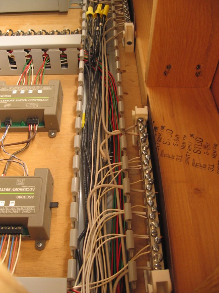
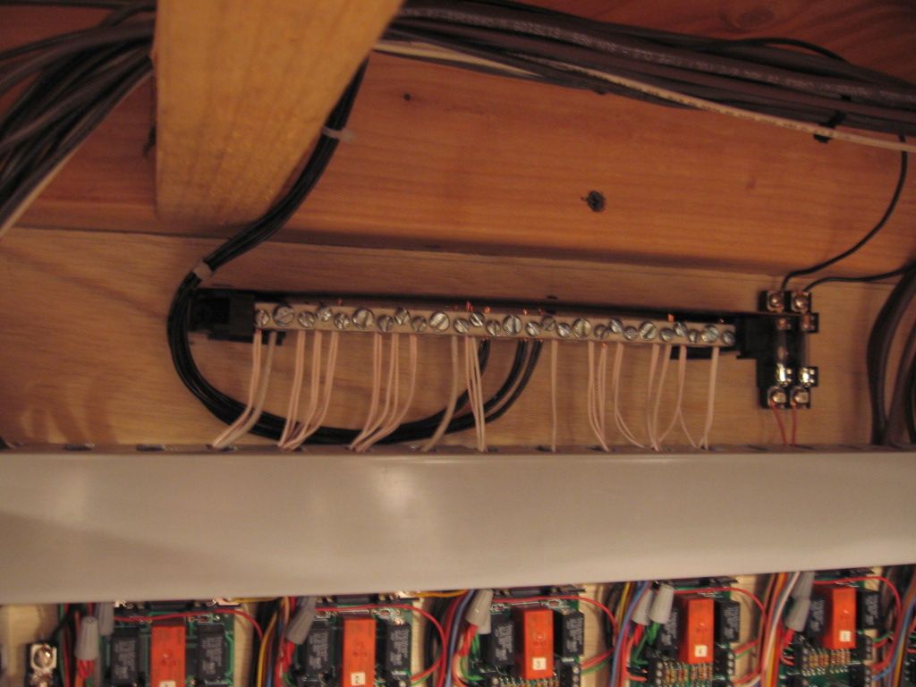
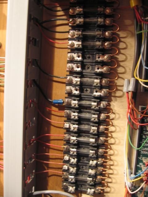
In the excellent thread "My new Train Room a work in progress", Charlie (from Michigan) posted a photo of a barrier strip leading to some drops he's been soldering:


His work is neat and impeccable, but I have a basic question: What is the purpose/advantage of using the barrier strips?  Is it just for the sake of neatness/maintainability?


I'm probably not letting go of the knowledge developed as a teenager when I learned all this stuff, but I would think that the barrier strip would represent an additional point of resistance for the current running from the transformer to the track.  Wouldn't a wire running directly from the transformer post to a soldered track lead result in more juice arriving to the track?

When I did my last layouts, I ran a wire directly from the transformer post, guided it under the table, and soldered multiple drops from the center rail directly to that wire.  I did more or less the same thing for the ground and ran several ground wires from phased transformers all around the underside of the layout.  I soldered the outside rails and other things needing a ground, directly to the ground wire for the return trip to the ZWs.


Is the purpose of the barrier strip simply to increase tidiness/flexibility or -- as so often happens -- am I unaware of some fundamental point?


Thanks in advance for your help.


Steven J. Serenska


Last edited by Serenska
Original Post

Replies sorted oldest to newest

Barrier strips are fine for wiring. Neat and easily changed. There is little or no issue with resistance. FYI, solder is not as low a resistance as a good crimp connection. Solder itself is not as low a resistance as copper. As to the wire terminal to wire terminal resistance, that would be an interesting investigation.

Used to organize and distribute railpower from power center to different power districts [or blocks] via multiple track connections. 


Enables convenient connection of AC Volt meters across the line and AC Amp meters inline for monitoring the railpower system.


One good place to connect PowerGuards or Transient Voltage Suppressors to snub voltage spikes.


IMG_1579

100_1159-001

IMG_2072

Attachments

Images (3)
  • IMG_1579
  • 100_1159-001
  • IMG_2072
Last edited by Dewey Trogdon

I believe they are best for maintenance and staged wiring. I can supply my power to that point and then handle the final connections later. If a problem occurs or a change is needed, it's simply loosen a screw.


They are not good for a distribution block(terminal bus block). The number of connectors that will fit is limited. After three on a post, it's a mess.


Finding some with jumpers to make a terminal bus block is a pain or cost prohibitive.


After wiring different layouts, they have their place, but other types must be used, too. Depends on the application.

Dewey and Mike. Really nice neat job on your wiring. My own is not so neatly done. I do use either barrier strips to terminate everything. What hasn't been mentioned is wire choice or colors. I find paired wiring just the thing for wiring lights or accesories. As far a colors. I'm all for bundling wires and keeping them neat. When a problem arises someday. The last thing you want is a neat bundle of wires all the same color. It may cost more to buy smaller rolls with different colors. If you run into a problem it will be worth it in the end. As it will be a lot easier to trace.

Out of curiosity, why put fuses in the accessory circuit or even the track power circuits?  Let the circuit breaker in your transformer handle the overload.  You will just be continually replacing fuses.  \


If you are using a postwar transformer with an excessively high amp circuit breaker like the postwar ZW, just build a circuit breaker box, like the one shown in Jim Barrett's "Jim Barrett in the Backshop, Volume 8" video.  It will handle all overloads in all four ZW channels and protect modern electronics.  I have built two of the circuit breaker boxes and they work great.


Earl

Originally Posted by EIS:

Out of curiosity, why put fuses in the accessory circuit or even the track power circuits?  Let the circuit breaker in your transformer handle the overload.  You will just be continually replacing fuses.  \


If you are using a postwar transformer with an excessively high amp circuit breaker like the postwar ZW, just build a circuit breaker box, like the one shown in Jim Barrett's "Jim Barrett in the Backshop, Volume 8" video.  It will handle all overloads in all four ZW channels and protect modern electronics.  I have built two of the circuit breaker boxes and they work great.


Earl

The breakers on PW type transformers are slow. Some branch lines are 22,even 26 gauge. A short in these lines may cook them before the breaker trips. 


If you want to wade through this post,it shows how I fused branch lines with polyswitch fuses. They work quite well and do not need replacement.


LINK


Dale H

Last edited by Dale H

Thy circuit breakers in Jim Barrett's video are the same circuit breakers used in modern transformers, and thus, provide the same short circuit protection as modern transformers.  I don't remember if Jim used Zener diodes in his video, but I used Zener diodes in the circuit breaker boxes that I built to protect against transient voltage surges too.


Earl

I hope the Zener diode you mention is really a TVS protection diode.  FWIW, the circuit breaker on some modern transformers are far too slow for my tastes.  The MTH Z500/750/1000 and the Lionel PowerHouse 135 are two examples.   To contrast those, the Lionel PowerHouse 180 has an excellent electronic breaker that reacts lightning quick to shorts.  Thermal breakers take seconds to react unless the overload is a direct short close to the transformer that pulls multiple times the breaker's rating.  Here's a popular 6 amp P&B breaker that's used on many transformers, including the MTH ones mentioned.


You'll notice that at a 200% overload the breaker can take from 2.2 to 15 seconds to trip!  IMO, that's simply too long.


CB

Attachments

Images (1)
  • CB
Last edited by gunrunnerjohn
Originally Posted by gunrunnerjohn:

I hope the Zener diode you mention is really a TVS protection diode.  FWIW, the circuit breaker on some modern transformers are far too slow for my tastes.  The MTH Z500/750/1000 and the Lionel PowerHouse 135 are two examples.   To contrast those, the Lionel PowerHouse 180 has an excellent electronic breaker that reacts lightning quick to shorts.  Thermal breakers take seconds to react unless the overload is a direct short close to the transformer that pulls multiple times the breaker's rating.  Here's a popular 6 amp P&B breaker that's used on many transformers, including the MTH ones mentioned.


You'll notice that at a 200% overload the breaker can take from 2.2 to 15 seconds to trip!  IMO, that's simply too long.


CB

I prefer fuses myself, but i haven't checked how long it takes one to blow and a TVS is a must have.

You also have the option of parallel power sources, which ramps-up  the system and faults, even more.  I use older PH 135, paralleled as a power source, on my layout. Part of the Fort Pitt High Railer's layout, turntable/roundhouse, has PH 180's paralleled.  After considerable arc and spark, rail, and wheel, welding. Each Track supply power, (there are 8 track circuits), is controlled by 7.5 amp fuses and accessories 3 to 5 amp fuses.  Fuse cost and replacement is simple and cheap compared to some the damage that was occurring.  Older IC Controls Block Power controllers would burn contacts and PC board traces/not work.  Even some of the recently installed Atlas Power Routing boards, rated at 8 amps, failed.  I fused the track circuits, used through the Atlas 6924 boards, at 3 amps, and have experience no damage other than fuse replacement.  You will find that the power routing, through switches is anything but a refined art.


You might also note that the fused track and accessory board simplifies trouble shooting, IMO.  Look for the burned fuse.  If it's a track circuit, one of 8, problem is only in 1/8th of the layout. 


Best wishes with your layout.

Mike CT  

Last edited by Mike CT

If you use an old PW transformer (or any others with slower breakers) on your modern electronic engines a PSX-AC made by DCC specialties is a very good option if you want very good circuit protection. It has built in voltage spike protection as well as many other features. It is very fast and can either be set for automatic or manual reset. It is slightly faster than the PH-180 breakers. These are not exactly inexpensive, but a real bargain when compared to replacement costs for your engine electronics.  

Add Reply

Post
×
×
×
×
Link copied to your clipboard.
×
×