
So I have been wiring a few DZ1000 switch machines in and the LED's are reversed between the controller and the switch machine. ( the controller is correct, the switch machine reads incorrect)

If I reverse the L and R, the colors are still reversed, but the LED's do not stay on, on the switch machine. If I change polarity, the switch machine to ground and controller to hot... there is no change... 


Has anyone seen this? Is this why later releases of DZ1000 controllers have eliminated the green LED?


How do I fix this?

Original Post

Replies sorted oldest to newest

Originally Posted by David Minarik:

The LEDs are polarity oriented.  Make sure you have them inserted correctly.  


    Is this why later releases of DZ1000 controllers have eliminated the green LED?


Don't know what you are talking about here?????????????

Both controller lights are red instead of Red and Green... (not sure if this was an older or newer batch of controllers)


Do I need to take the switch housing case off to swap the LEDS?

Last edited by J Daddy

Both controller lights are red instead of Red and Green... (not sure if this was an older or newer batch of controllers)


Do I need to take the switch housing case off to swap the LEDS?

Those are very,. very old DZ1002's and the LEDs are soldered in place. The DZ1002 should be replaced unless you want to unsolder an existing red LED and reorder a green one.


Further, to swap LEDs in the motor, just swap and rotate the LED 180 degrees when you reinsert it. If you don't rotate them, you can wind up with both on and off together.


The same goes for the controller.

I had to wire up over 50 Z 1000's on my layout, and here is the lesson I learned:


Before the switch is installed make a temporary connection between the controller and the switch machine. Make sure the LED's on the switch machine and controller reflect what you want to see on the control panel and switch machine along with the direction of travel through the switch. Reverse the red and green LED's as necessary. If you are wiring the switches later, be sure and mark the controller and switch machine as a set.


Those LED's are no fun to move around when you have a switch in a hard to reach part of the layout. I still have a few Z 1000 machines that do not match the controllers on the panel, but at least the controller's LED  relates correctly  to the direction of travel through the switch.


I recall times when the wife told me to turn off the lights in the train room and come down stairs, as she had heard enough my foul language when wiring my Z 1000 switch machines.


Richard

Originally Posted by Ed Walsh:

Is there anything on the led to indicate polarity?  I swapped the LEDs on a controller awhile ago and am getting weird results.  I was just wondering how to tell if I have 1 or both reversed.


Ed

Ed,

When an LED is new, the long leg is the anode(+). It may also be wider. They typically get tied together for current in. The cathode(-) is usually separately wired to the switch.

Prongs are the same.  One side of each LED, near a prong, is flat.  If you look at the switch motors, you'll see the light holders aren't round, but have a flat side.  Match the flats.  You may need a magnifying glass if your vision isn't 20-20.


If you have very old controllers, contact DZ about replacing them.  I replaced all mine with the new snap type, for about $2/per.


I've learned a lot about these devices while changing over to them in the past 6 months.  I like to press the button by the dark LED to have the switch move in that direction, which means I occasionally have to switch the bulbs in the controller, a simple task.


If you use one controller to throw 2 machines, there are some special tricks you'll need to use so both bulbs don't light. I won't go into the details unless someone has a need.

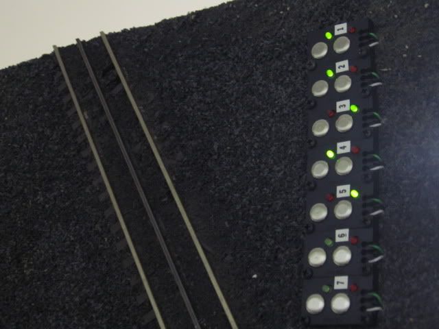
Per request, here’s how I handle the DZ 1000 switch motors.  First, I mount the controllers on my control panel, which has a sketch of the layout.  I mount the controllers over the switch locations.  I insist that the illuminated LED be over the branch for which the switch is set, and that if I want the train to take the other route, the button to press is over that route; in other words, adjacent to the non-illuminated LED.  I make no exceptions to this rule.  If there is a location where one controller controls 2 switches, I mount it so the lights are in the most logical position to indicate route.

1. If, after wiring a switch, I find that the button to press is adjacent to an illuminated LED, I reverse the controller LEDs and mount the controller accordingly.  

2. If, after wiring the switch, I find that the buttons move the switch in the wrong direction, I switch to the R and L connections on the switch motor.  Then apply 1 above

Now for when I want to have a single controller throw two switches, such as in a crossover.  This can get complicated.

3.  If I have a simple crossover, two left-handed or two right-handed switches with the curved sections connected to each other, and the switch motors in the same position on each switch, simply connect the two R terminals together and the 2 L terminals from the switch motors and run to the controller.  Then see above.

4,  If I have two lines intersecting at a cross track, and install a track permitting the train to go from one line to the other, if I use a right-handed and a left-handed switch, with their curved sections connected, then on one of the switches I must reverse the location of the switch motor, which I can do in one of two ways.  I can either rotate the switch motor 180° on the same side of the switch, or relocate it to the other side of the switch.  Then  simply connect the two R terminals together and the 2 L terminals from the switch motors and run to the controller.  Then see above.

5. In two locations I have a crossover on a curve, so that the straight side of one switch is connected to the curve of the other.  In one of these, have used a double-curved switch for the outside track; in the other, the parallel main lines split.  In both, I am wanting the controller to show green when one (and only one) of the switches is set for the train to take the curved portion.  Step 1 is to mount the switch motors—see 4. above—so that when both Ls are energized both switches go in the one desired direction and when both Rs are energized they go in the other.  The apply 1 & 2 above.

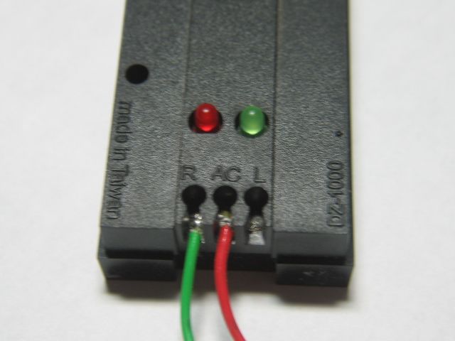
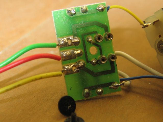
The switch motors are ingeniously designed, with a small motor, a microswitch, and 2 diodes to control the direction of current flow through the motor.  LEDs are polarity sensitive.  Thus, sometimes it will take a bit of experimenting to get things right.

Do not use the DZ controllers to control any other brand of switch.  They are designed for the tiny draw of the DZ1000 switch motors, and can’t handle the heavy current required by solenoid-type switch motors.

Robert,

Do not use the DZ controllers to control any other brand of switch.  They are designed for the tiny draw of the DZ1000 switch motors, and can’t handle the heavy current required by solenoid-type switch motors.

That's interesting.


Twelve years ago, when I built the lowest level of my layout for the subways, in addition to the Gargraves and Ross turnouts that I used, I also used a pair of Lionel Super O (O36) switch tracks. I've been controlling these two Super O switches with DZ1002 controllers, just like the rest of the switch tracks.


While I don't use the two Super O switches often, I have used them regularly over the years without any ill effects. The only idiosyncrasy is that, no matter what I tried, I couldn't get the controllers to light the LED over the button that was pressed. After literally hours of trying every combination that I could imagine, I gave up. These two switch tracks display the LED over the button that was not last pressed.

Last edited by Barry Broskowitz

Barry, Dennis Zander of DZ advised me of this limitation of use when I spoke to him a few months ago.  The key to your "success" is the statement that you don't use them often.  According to Dennis, these controllers are sized for the switch motors' 50ma current draw.  Solenoid motors draw over an amp and, if you do not have the feed cut by connections in the switch motors, there is a major arc at the controller.


As you know, I control many of my switches through 3 AIUs, and some of my switch motors (a decreasing number) were NJI switch motors.  To preserve the AIU relays from arcing, I wired the NJI switch motors to cut the current when the switch had thrown.


Your lighting problem is probably due to the fact that the Lionel motors do not contain diodes and this gives polarity problems for the controller. 


I have several Atlas switch on the layout, and have been removing the solenoids and adding DZ1000 switch motors.  They work fine.

Last edited by RJR
I have this problem. Yes it can be fixed. I just wanted to add my two cents. Several comments above advise you to remove the lights by pulling them straight up. that is fine. But just be darn careful how you put them back in. 1 prong is longer than the other. It does make a difference. And, if you have any other switch boxes you may want to try them first before you start switching lights around. If you use a left handed box on a right handed switch you will get the result you're getting. I made the huge mistake of throwing all my switch boxes into a pile. I paid for it by spending hours getting all of the lights correct. From that point forward, I never remove the switch boxes from the packaging until I'm ready to install and wire them. That way I know I have the correct handed switch box with the correct handed switch. I learned the hard way.

A couple of pictures.  Green and Red can be reversed.

Note the flat side bottom left (red) diode. Flat side for the Green diode is top, not visible in this picture.   DZ 1000 was dismantled to reconnect wire leads that had fallen off.


The four, plug-in, diode connections.  Left center of picture.

Last edited by Mike CT

Charlie,


Fantastic control panel.  I did something similar to your control panel except that I applied the layout lines by hand which turned out, just OK.  As perfect as your lines are I am guessing you generated the layout lines on a computer and printed it out.  I was hoping you could provide the details (size, software used, are you using a clear cover over the printout, etc.). 


Since this thread is about DZ issues maybe you could let me know via a new thread or to my email.


Thanks,

Ed

Charlie, I also would like to see the details of how you printed the control panel.


I went the opposite direction, from toggles to DZ1002's.  The double throw center off momentary toggles looked great.  After 20 years without lights, I started adding signal light, and quickly found that the LEDs, with associated resistors , and diodes for use with non-DZ1000 motors, created too much wiring behind my control panel (50 switches and 70+ toggled blocks).  So I have been installing the DZ1002s.

We (Fort Pitt High Railers) used the DZ 1002 for several cross over switch pairs. We also paralleled two DZ 1002 to each switch motor at two different locations.  Note that green is through and red is out.  DZ 1002 and DZ 1000 have to be wired as the schematics show, which may require flopping the red and green led's.

Note how the red and green Led's aren't in a straight line.


The control panel diagram was created by forum member willbacker45.  He offers this as a service for a reasonable fee.  I then took the art work and had Kinkos print and laminate it.  Then that is attached to a piece of 3/16 lexan. 


There is alot of wiring behind the panel, however it's worth it if this is the look your going for.  The panel is 8 1/2 x 11 and all of the indicator lights are LED's.


Last edited by MichRR714

Add Reply

Post

OGR Publishing, Inc., 1310 Eastside Centre Ct, Ste 6, Mountain Home, AR 72653
800-980-OGRR (6477)
www.ogaugerr.com

×
×
×
×
Link copied to your clipboard.
×
×