Can you use this for an Atlas switch?
Can you make an entire layout wireless control without an elaborate control panel? Thanks for the help.
|


|
Can you use this for an Atlas switch?
Can you make an entire layout wireless control without an elaborate control panel? Thanks for the help.
Replies sorted oldest to newest
Mine is, there are no physical controls. The LCS with iPads operates the entire layout. 45 turnouts, 8 power districts, 45 blocks, all lighting, uncouplers and action cars. Cab 2 handhelds and iPhones operate the engines.
In clarification, the wireless part is the iPad, Cab 2 and iPhones to the base. The LCS device outputs are hardwired to the layout items they control. The LCS devices are interconnected with a PDI cable loop.
Well, the LCS devices are actually connected using that special (and I might add expensive) cable. ![]()
That is an understatement. I have 47 PDI interconnecting cables in the LCS loop, that is $700 just to connect all the LCS components. Plus $5,000 of LCS components.
Yes, I have Atlas O switch machines, DZ1000 switch machines connected to the ASC’s for remote Cab1-Cab 2 control. The directions that come with these electronic devices show how to wire them up with SC2’s, and the normal way. Good question. Happy Railroading Everyone
@AmFlyer posted:That is an understatement. I have 47 DB9 interconnecting cables in the LCS loop, that is $700 just to connect all the LCS components. Plus $5,000 of LCS components.
What did you buy for $5,000? I have more like $1,500 in a few CSM2's, a bunch of the breakout boards, the Wifi and Ser2. I also have some of the sensor track sleds for non-Lionel track, but I haven't done any installation of those yet. I have to work on my layout mapping on the iPad so I can represent all the switches.
AmFlyer, are you referring to PDI cables or are you converting to DB9 connectors & wiring for LCS interconnects?
One WiFi, 3 Sensor Tracks, 8 BPC2's, 30 ASC2's, 4 STM2's and 5 Boosters. This count includes 5 spares. In 4 years two ASC2's have failed and a third one works about half the time. No other type of LCS device has failed. The ASC2 failure mode has been failure to hold programming when turned off.
Regarding the large ASC2 count, in addition to the 45 turnouts there are a lot of uncouplers, action tracks and lights. The layout was built in 15 separate modules. A design decision was made that no LCS output wires would cross a module joint. Only power wires and PDI cables cross module joints. This means that an LCS component may not have all outputs used because a given module may not have enough of each type of device on it to require all the outputs of the LCS components mounted on that layout module. This design decision added about 15% to the LCS device count. Given that the layout was built in Miami, disassembled, shipped, reassembled and tested in my house this was the right decision.
Sorry, I mean the PDI cables. I do have some 5' DB9 cables to connect the sensor tracks to their control boards. I will edit the posts.
I don't think a Y cable is possible. The LCS PDI comms are all point to point. 115.2Kbaud. Each box receives a PDI packet and, if it is not addressed to that box, re-transmits it to the next box it is connected to. A Y cable would introduce possibilities of packet collisions.
Have you measured latency between the Legacy Base and LCS box #37?
We have not measured latency. Whatever it is it is undetectable by the user (me) when using an ipad.For example BPC2 #37 turns the track power on and off to the 6 tracks in the passenger yard. BPC2 #4.5 does the same for some of the freight yard tracks. Both appear to react as soon as the icon is touched on an iPad. I currently have three iPads in use with the LCS. The icons on the two iPads not used to actuate the control respond simultaneous with the iPad that was used. The LCS capabilities are impressive.
The real problem with the system was voltage drop, that was cured with the 5 amplifiers (powered joiners) in the system.
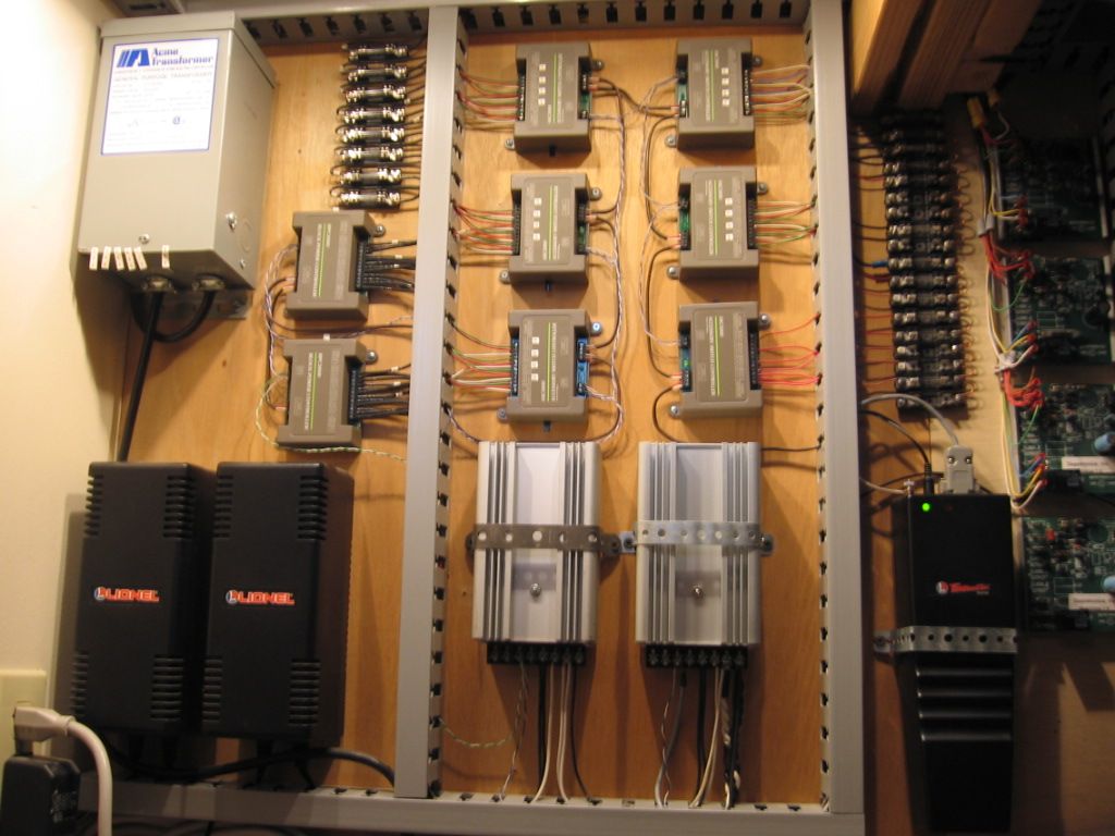
Six IC Controls ASC's, Accessory, Switch Controllers, before Lionel, each controls (4) Atlas switches. Handheld remote/ RF connected to the Command Base has switch control buttons, programming each switch with a number 1 through 24. Top picture center. Command base cable is connnected to one of the silver box, TPC's Track Power controllers. The RF signal is daisy chained, with Cat 5 wire between the 10 IC Control devices, and the command base lower right. As pictured, the system, 20 years later, still works well. Both, newer Legacy, and MTH DCS controls, never worked as well as this original control system.

Mike,
I never tire of seeing this image. Your wiring/organization is a real high-water mark.
We're in the process of planning our permanent layout and we intend to use only the LCS system with iPads (likely in fixed stationary positions) rather than mechanical control panels.
Access to this requires an OGR Forum Supporting Membership
