Replies sorted oldest to newest

DON'T CUT YOUR ROSS SWITCH!!!  The non-derail is simply a small section of completely un-powered "dead" rail which you attach one wire that is connected to one wire on the switch machine.

Good advice above.  Go to Ross Page--study diagram.  Second, add a small section of track adjacent to Ross switch and use as a dead rail section to activate the turnout machine.

That's why I prefer the set-up of Gargraves switches.  These switches are dead from end to end.  In others words, power will NOT pass from one end of the switch to the other.  This makes it simple to wire the non-derailing function.  This is versus Ross where the power passes completely through the switch.

Basil,

Ross does not make the switch machines.  If you bought the switches from Ross with the machines already attached, the are made by Z-Stuff.  You did not say which machines were attached (DZ-1000 or DZ-2500), but the Z-Stuff web page has good diagrams for both.

I doubt anyone has a good picture because the wiring would be under the switch or table, out of sight.

rrman posted:

On my layout I added a half section of track before the non derail to give the Z stuff motors time to fully operate before the wheels hit the points.  Works well if you are a fast runner, or motor is a little lazy or points slightly bind.

To add on to my reply, I paint the spot where the derail piece starts to insure no train wheels are on that section.  Also serves second purpose insuring the cars/loco are back enough to avoid passing train side swiping.

Basil, these switches were purchased as non-derailing with Z-Stuff switch machines.

This photo shows the turnouts secured with track screws.  This pair of turnouts is on a shelf so the terminal strip is on the same surface as the turnouts.  The small yellow and green wires are the "trigger" wires.

SecureNo8

Pair8nd

These are #8 turnouts that have long enough rails to activate non-derailing.  The tan cable is telephone wire that I use as switch signal wire.  The green arrows point to the soldered connections of those wires to the "trigger" tracks.  The green #1s indicate the hot glue insulation to maintain electrical conductivity between the "trigger" tracks.

Attachments

Images (2)
  • SecureNo8
  • Pair8nd

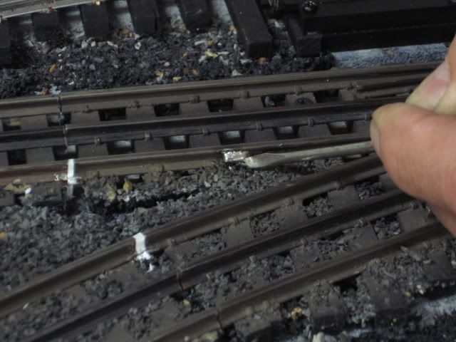
Switches in place the isolated sensor rail section(s) were cut-in, and wired after the switches were installed.

Note the styrene insert in the cuts as part of the isolation.  Wire attached/soldered.

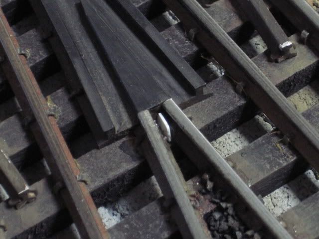
Where the short rails meet at the frog, I had to add styrene to separate the two rail sections.

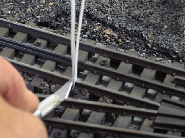
Styrene strips. Cut and fit, CA applied to hold in-place.

Last edited by Mike CT
Mike CT posted:

Switches in place the isolated sensor rail section(s) were cut-in, and wired after the switches were installed.

Note the styrene insert in the cuts as part of the isolation.  Wire attached/soldered.

Where the short rails meet at the frog, I had to add styrene to separate the two rail sections.

Styrene strips. Cut and fit, CA applied to hold in-place.

I was having an issue today after installing two ross #101.  I could not get the non derailing to work, tried everything.  The 072 and 072Y worked no problem.  I did not put anything between the two rails that meet at the frog.  After seeing your second picture, then looking at the switches, the two rails do touch at the frog, I am sure this is causing my issue.  I will try to isolate those two rails, or cut the rails just to the outside of where they touch. 

Add Reply

Post

OGR Publishing, Inc., 1310 Eastside Centre Ct, Ste 6, Mountain Home, AR 72653
800-980-OGRR (6477)
www.ogaugerr.com

×
×
×
×
Link copied to your clipboard.
×
×