My control panel has several Arduino microcontrollers, several 20x4 LCD character displays, several RS485 communication boards, and a few other digital devices that require BOTH a 5vdc general supply, as well as 5vdc logical high and low signals to tell them what to do.  I'm powering my Arduinos with a 9vdc wall wart (the Arduino voltage regulators step it down to 5vdc), and the rest of the electronics in my control panel with a 5vdc wall wart.  All grounds (negatives) are tied together.  The positive power from the two wall warts are INDIRECTLY connected together which is my concern.

I'm wondering if I might be breaking any rules by using +5v output from the 5vdc wall wart to power my digital devices (except the Arduinos), and feeding those same devices 5v (logic high) signals coming off of my Arduinos - which as I say have a separate DC power supply?  The 5v lines from the two sources are not connected directly -- but if I'm powering the device with one 5v supply, and feeding it digital logic from another 5v supply -- is that a problem?

Thank you so much for your thoughts!

Randy


Attachments

Images (5)
  • P&SCRR Block Diagram: P&SCRR Block Diagram
  • P&SCRR Panel: P&SCRR Panel
  • P&SCRR Panel interior: P&SCRR Panel interior
  • P&SCRR view: P&SCRR view
  • P&SCRR Poster: P&SCRR Poster
Original Post

Replies sorted oldest to newest

As long as the grounds of both supplies are connected together, there should be no problem. In some rare cases you could get noise spikes. I would consider transients (or undefined states) when I turn everything on. You don't want the possibility of commanding an accessory or switch in multiple ways simultaneously.  If you are really worried, you can use opto-isolators on all the signal lines.

-Lad

How you've explained things sounds just fine, though I do concur that you'll want to make sure the supply power for the Arduinos is filtered just so you don't have any problems.  Your best bet is to use optocouplers on all the I/O pins that you want to perfectly isolate them from any interference.  

As a second note, it isn't needed at all, but the Arduinos are more energy efficient if you power them with 5VDC on the header rather than using the onboard regulator.  If you are driving a lot of current you may also get better results this way as the on board regulator may not deliver enough current to all the I/O pins.  

My favorite high current, well filtered, 5VDC supply is a computer power supply.  $15 will get you a 25 Amp+ 5 volt supply.  

JGL

crood58 posted:

how do you typically modify the power supply to power the arduinos with 5 volts?

The ATX standard computer power supply is pretty straight forward for simple +5VDC and +12VDC.  There will be one large 20 pin connector that would normally connect to a computer's mother board.  On this connector you can use a jumper wire, or cut the wires and use a toggle switch from the green wire to any black wire.  This is the power switch for the power supply.  

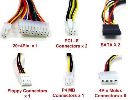
On all the other connectors there will typically only be 3 colors present, Black, Red, and Yellow.  Black is ground, Red is +5VDC, and Yellow is +12 VDC.  

Here is a picture of the various connectors:  for experimenting I tend to stick breadboard jumper wires into the floppy connector.  For more permeant things I cut off one of the Molex connectors and solder the wires to whatever they are powering.  

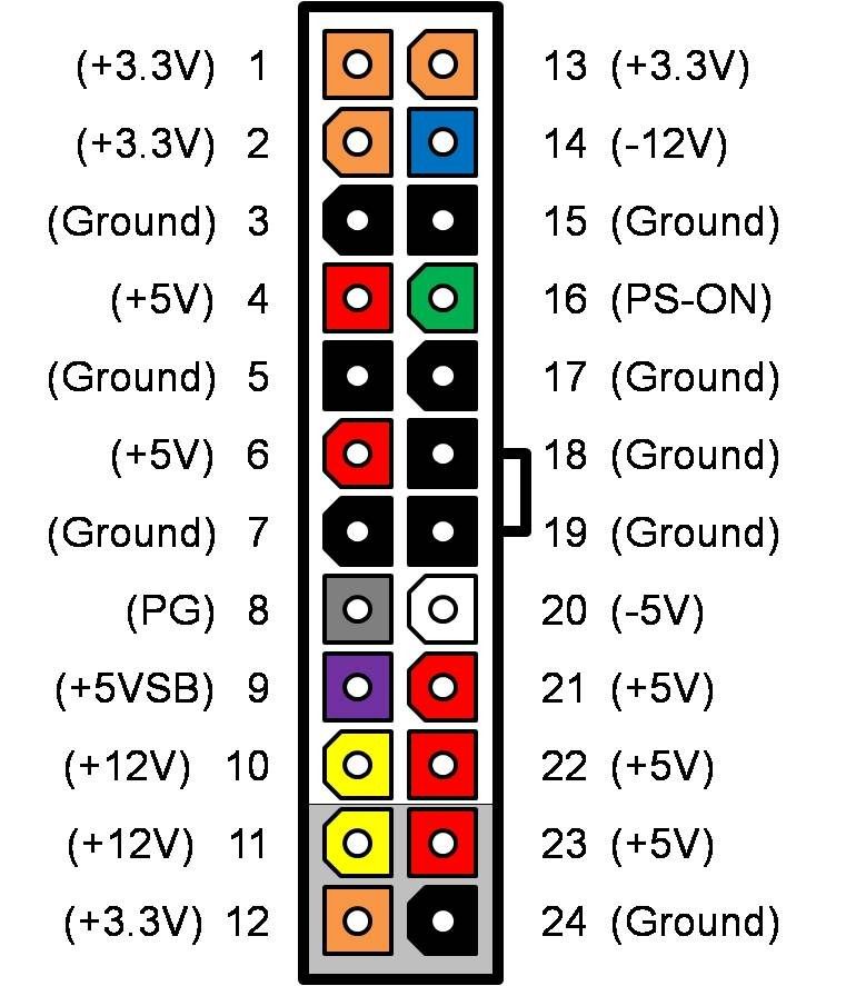
And here is the 20 Pin connector:  

This shows the other voltages available, as well as the color of their wires.  As a note negative 5 volts is no longer standard on all ATX power supplies, so if you need it for some reason, make sure the power supply you chose actually has it.  

If you want to get really fancy, the grey wire (pin 8, also called 'power good') can be used to detect that all voltages are at their proper level.  

Here are the outputs on on the cheapest ATX supply from NewEgg:  

+3.3V@28A, +5V@36A, +12V@16A, -5V@0.5A, -12V@0.8A.

Short version:  Green wire switched to Ground for power switch, Black=Ground, Red=5v, Yellow=12v.  

JGL

You can run 50 things from the 5V, all those outputs are parallel inside the supply.  Occasionally, they will split the 12V on some supplies from two separate outputs, but that seems to have fallen out of favor.  Also, you have the +5VSB, that's a low current output that's always active. 

Note that some (but not all) ATX power supplies need a load on either the +5V or +12V outputs to properly regulate

PS: that's a 24 pin connector, which is standard on ATX power supplies for the last few years.

Yep, As GRJ says, there is just one source for each voltage.  Many wires are used on the 20(+4) connector so that the current can be spread between them, and between several traces on the motherboard.  When last I shopped for a high end power supply, multiple 12v lines where still in vogue. Not sure if that has changed, but even then it was a feature found only on power supplies in the $100 range... well beyond what is needed for powering some electronics experimentation.  

GRJ, I suppose my calling it a 20 pin shows from what time period I was most into computers.  The ATX standard was fairly fresh when I was learning how to put together a computer, and I still think of it as a 20 pin and a plus 4 pin. (which I think is still the official designation, 20+4)  I also have a number of high end mother boards that had a molex connector for additional power before the 4 pin MB power was added.  It seems lately motherboards have enough power, I don't know of any using more than the standard connections now.  

Anyway, seriously digressing here... 

JGL

JohnGaltLine posted:
crood58 posted:

how do you typically modify the power supply to power the arduinos with 5 volts?

The ATX standard computer power supply is pretty straight forward for simple +5VDC and +12VDC.  There will be one large 20 pin connector that would normally connect to a computer's mother board.  On this connector you can use a jumper wire, or cut the wires and use a toggle switch from the green wire to any black wire.  This is the power switch for the power supply.  

On all the other connectors there will typically only be 3 colors present, Black, Red, and Yellow.  Black is ground, Red is +5VDC, and Yellow is +12 VDC.  

Here is a picture of the various connectors:  for experimenting I tend to stick breadboard jumper wires into the floppy connector.  For more permeant things I cut off one of the Molex connectors and solder the wires to whatever they are powering.  

And here is the 20 Pin connector:  

This shows the other voltages available, as well as the color of their wires.  As a note negative 5 volts is no longer standard on all ATX power supplies, so if you need it for some reason, make sure the power supply you chose actually has it.  

If you want to get really fancy, the grey wire (pin 8, also called 'power good') can be used to detect that all voltages are at their proper level.  

Here are the outputs on on the cheapest ATX supply from NewEgg:  

+3.3V@28A, +5V@36A, +12V@16A, -5V@0.5A, -12V@0.8A.

Short version:  Green wire switched to Ground for power switch, Black=Ground, Red=5v, Yellow=12v.  

JGL

John,

Thank you for the information. I haven't messed with one of these in awhile, probably 7 years when I bought my last computer. I like the idea of using pin 16 for a power switch. This is sure going to come in handy for the things that need 5 volts to 12 volts of DC power. Especially the 5 volts for the arduinos. 

Chris 

Add Reply

Post
×
×
×
×
Link copied to your clipboard.
×
×