
Chris,
Really great work. Question, what is the angle between each whisker, or track spur, leading into the round house? I plan to have a Korber too, but not for a while and after the turntable is laid. Thanks.
|
|
Chris,
Really great work. Question, what is the angle between each whisker, or track spur, leading into the round house? I plan to have a Korber too, but not for a while and after the turntable is laid. Thanks.
Well, I just hooked up my lighting. 3 volts wasn't enough. Switched to the adjustable side of the power supply and accidentally smoked ALL 16 LEDs. Now I have to replace them all. I'm walking away for a few days. I'm not a happy camper right now. The power supply isn't regulated, so the load was too much for the preset 3 volt side.
@CAPPilot posted:Chris,
Really great work. Question, what is the angle between each whisker, or track spur, leading into the round house? I plan to have a Korber too, but not for a while and after the turntable is laid. Thanks.
I'll try and get you an answer. Dont know off hand. But someone else with a #320 may know.
Ron, I can’t answer as to what degree the tracks are. If you go to Mr Muffins site. The Roundhouse has a couple of PDF’s that show dimensions as to how far the roundhouse has to be placed back from the bridge to get a straight run into the stall. It shows both the Bowser and Millhouse River.
Sorry to hear about your LEDs. I am using them more often as I get further along into detailing my interiors. #1 rule is to remember they are current driven, not voltage driven. It’s more work but the best and safest way to drive them is to put dropping resistors in series with each LED. I like to set one up with a 1K resistor using a variable DC power supply and dial up the brightness desired. I can note the current needed and also figure out if I can safely run them at the full rated voltage of my variable power source in case it gets accidentally cranked.
Here’s a layout testing pic of the leads coming out with individual resistors for each led. More work but can save some aggravation. I should note I don’t believe in LED driver power supplies, my preference is do it this way. You could also use different value resistors to make some lights dimmer than others if needed.

Thanks for the input Norm.
This is what I'm using to power the LEDs. It has a 3 volt side and an adjustable side. The LEDS weren't bight enough with just the fixed 3 volt setting. So I switched to the adjustable side and accidently put in too much voltage and fried the LEDS. It adjusts up to 20 volts. I did have a meter on it, but sinces its mounted on the bottom, I couldn't watch the LEDs and adjusted it too far.
I checked all of the outputs on the board and they are the same. All the + are connected together and all the - are connected together.
I have the LEDs on one frame paralleled together, then into the board to one output. Another frame into another output, etc.
1 x power distribution board self adapt distributor HO N O LED street light hub | eBay
Any suggestions on a regulated 3 volt power supply? Seems that would be the best of all worlds.
Also, what about the Woodland Scenics lighting system? Anyone using that for LED lighting?
Thank you everyone for the kind words and likes.
Like I posted earlier in this thread, I also found that the goose neck hanging lights I had installed were not bright enough for my tastes to light up the interior properly.
My solution was to install LED strips on the underside of each of the rafters running lengthwise from front to back. I purchased pre-wired LED strips with resistors, such as the ones below, that can be powered with 12v-18v AC or DC power.
10pcs Pre Wired White Light Strip 6 LED SMD Light Self Adhesive Flexible 12V-18V | eBay
I bought a bag of Plastruct U-Channels (about 1/4" wide, I think) to first mount to the underside of the rafters in order to hide the LED strips and painted them brown to match the wood-colored rafters in my RH and cut them to length. Since they come white and your rafters are white, you probably wouldn't even need to paint them. I trial fit the adhesive LED strips into the channels (they're snug, but fit) and secured with CA glue and glued the assembled channel to the rafter underside and then ran the red and black wires out the back and down the wall tucked in close to the uprights and then out the bottom of the RH to be hooked up to a power supply. I also painted the wires brown to blend in and you would probably want to paint the wires white before installing.
The channels, led strips and wires are virtually invisible to anyone viewing the RH. They provide plenty of additional "hidden" lighting and I was completely satisfied with how it came out. One of those deals where more than likely only you will know they're there.
If you think you want to try this route, let me know. I have almost a full bag of the Plastruct channels that I'll likely never find another use for that I can send you.
@Richie C. posted:Like I posted earlier in this thread, I also found that the goose neck hanging lights I had installed were not bright enough for my tastes to light up the interior properly.
My solution was to install LED strips on the underside of each of the rafters running lengthwise from front to back. I purchased pre-wired LED strips with resistors, such as the ones below, that can be powered with 12v-18v AC or DC power.
10pcs Pre Wired White Light Strip 6 LED SMD Light Self Adhesive Flexible 12V-18V | eBay
I bought a bag of Plastruct U-Channels (about 1/4" wide, I think) to first mount to the underside of the rafters in order to hide the LED strips and painted them brown to match the wood-colored rafters in my RH and cut them to length. Since they come white and your rafters are white, you probably wouldn't even need to paint them. I trial fit the adhesive LED strips into the channels (they're snug, but fit) and secured with CA glue and glued the assembled channel to the rafter underside and then ran the red and black wires out the back and down the wall tucked in close to the uprights and then out the bottom of the RH to be hooked up to a power supply. I also painted the wires brown to blend in and you would probably want to paint the wires white before installing.
The channels, led strips and wires are virtually invisible to anyone viewing the RH. They provide plenty of additional "hidden" lighting and I was completely satisfied with how it came out. One of those deals where more than likely only you will know they're there.
If you think you want to try this route, let me know. I have almost a full bag of the Plastruct channels that I'll likely never find another use for that I can send you.
I'll let you know. Just finished replacing all 18 leds. I think my board isn't strong enough for all of them.
@Bob posted:Looking good, Chris! You can't have too much "stuff" in the roundhouse.
Bob,
You have a source for all your internals?
The linear regulated power supplies I get from eBay seem to work well and can be found under this description:
AC/DC to DC Converter Adjustable Voltage Regulator Power Supply Module 5V 9V 12V
They are $3 each. Keep in mind you have to use dropping resistors in series with each LED to drive them. You could also run groups of LEDs with a single resistor if you calculate the current correctly. I still like individual resistors for each LED so you’re not dissipating too much heat off the resistor.
Here’s a vid I did on my car and diesel shop lighting where I try to describe my planning and installation of my home brewed LED lights:
One other consideration for running the LED leads is to install some busbar using brass or copper rod. I did this in my Altoona Model Works roundhouse to help manage the wiring:

Thanks again Norm. Really appreciate all the info and help. I did manage to get the LEDs changed yesterday and I put them back in place this morning. Sorry for the blurry pictures, but with not enough ambient light it makes it difficult for the camera to focus. The power board is running at about 2.6 volts. I have good light coverage. It just it seems, the LEDs seem a bit dim to me, I'm afraid to try and make them any brighter in fear of blowing them again. I think I can live with it. I had to remove the sides in order to change the LEDs. Two steps forward, one step backward.
Now to get Cap his answer.


Looks neatly done with plenty of light. I’m no expert on lighting. But I wouldn’t evaluate the lighting to much till you get the roof in place.
@CAPPilot posted:Chris,
Really great work. Question, what is the angle between each whisker, or track spur, leading into the round house? I plan to have a Korber too, but not for a while and after the turntable is laid. Thanks.
Ron,
The tracks appear to be approximately 8-10 degrees using the center rail. More like 8*, you decide.


@Jayhawk500 posted:Cap,
The tracks appear to be approximately 8-10 degrees using the center rail. More like 8*, you decide.
Chris,
Thank you for going to the effort to do this. I like this Korber roundhouse but I am not going to start it until well after the tracks are laid. Trying to get the angle off the drawings showed between 10° and 12°, your picture shows a little less. I think I will go with 10°.
Again, your work is great. Really appreaciate you letting us follow along with your construction. Will really help me.
@CAPPilot posted:Chris,
Thank you for going to the effort to do this. I like this Korber roundhouse but I am not going to start it until well after the tracks are laid. Trying to get the angle off the drawings showed between 10° and 12°, your picture shows a little less. I think I will go with 10°.
Again, your work is great. Really appreaciate you letting us follow along with your construction. Will really help me.
Thanks for the kind words Ron. Glad to help!
@Jayhawk500 posted:Korber Window Install
I have completed the first rear panel of the roundhouse. The "small" Korber laser cut windows are actually too big for my roundhouse. So I had to trim and sand them down to get them to fit into the openings. Oh, did I mention I was inlaying them into the walls? They are mounted flush with the interior side of the wall. These windows are very delicate, but they are strong enough to stand up to the cutting and sanding. Once satisfied with the fit I was on to the finish. I opted to go with the kelly green, same as the doors and skylights. Then glued them into the openings with super glue to hold them in place. I sealed the window opening with wood glue, using my #11 X-acto knife. Finally, I painted the glue to hide it. I still have light bleed through, But another coat of paint w/ a #00 brush will take care of that. From start to finish, the process for one window takes me about 2-3 hours. When it's all said and done, I'll have about 44-66 hours in just the windows. I am one of these guys that likes to see instant gratification in my work. It's hard to walk away sometimes and allow the paint or glue to dry.
Until next time...
Nice work! That came out nice.
Just a note, the windows are actually not too small rather they are designed to overlap the opening from the inside and glue to the inside of the wall. This was in part because the molded wall window openings have some variation from window to window.
Thank you for the nice comment. Yes, there's lots of variations between windows. Having them inset, I think, gives a more prototypical installation.
I have the cardboard roof panels cut and trimmed. I had purchased 5 3-ply Midwest Products 1/32 x 12 x 24 Birch Plywood panels (252-9836) from my local Menards store to use instead of the cardboard panels. The first 2 panels were nice and flat, the other 3, not so much. I had put weights on them, bowed them the opposite way, tried to let gravity and Mother Nature have her way and they're still bowed. The Menards store has 2 more sheets and they're just as bad as the 3 that I have. Is there anyway to flatten out these panels? I don't see Menards getting anymore panels in until these are gone. Should I wet them and weight them down again? I'm at a loss currently. Any help would be greatly appreciated.
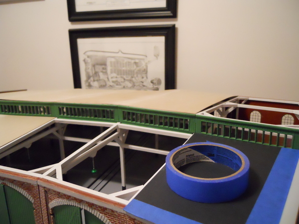
Here's the lighting with the roof on the structure. I can paint the under side white to reflect more light when the time comes. Also, these kits come with black "gravel" for the roof. I'd like to use a gray "gravel" to simulate the pea gravel normally used on roofs, and use the black around the smoke jacks to simulate the sooty gray gravel. Anyone have such a source or link to said product?


Thanks in advance....

@Dave_C posted:
Great, Thank you very much.
Good Morning Everyone,
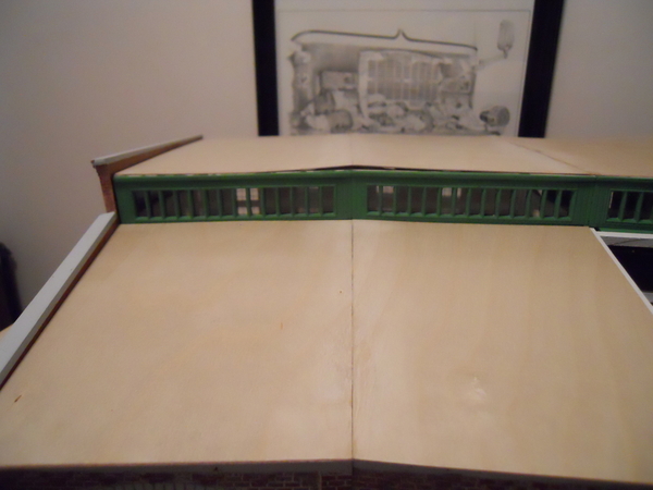
Just a quick update on my build. I have completed fitting the cardboard roof panels to the structure. I then cut out the roof panels in 1/32 plywood in the hopes of having a removable wood roof. Currently, I'm disappointed in this process. I am now comtemplating Richie C's idea of a lexan roof. The wood roof panels wont lay flat unless I put some wood strips underneath to keep them flat. I'm working on trying to get my last plywood sheet to lay flat. I have attached some photos. The panels are glued edge to edge and will lay flat if some weight is added.
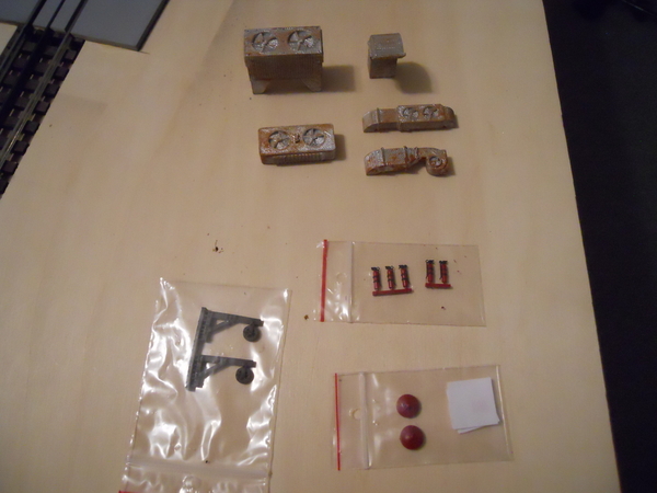
I have also purchased some more interior items and some roof mounted venting systems. Being a retired firefighter, I have to have extinguishers and alarm bells.
And as promised, my CSS and Daylight in the stalls. The tenders will stick out of the doors.
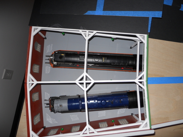
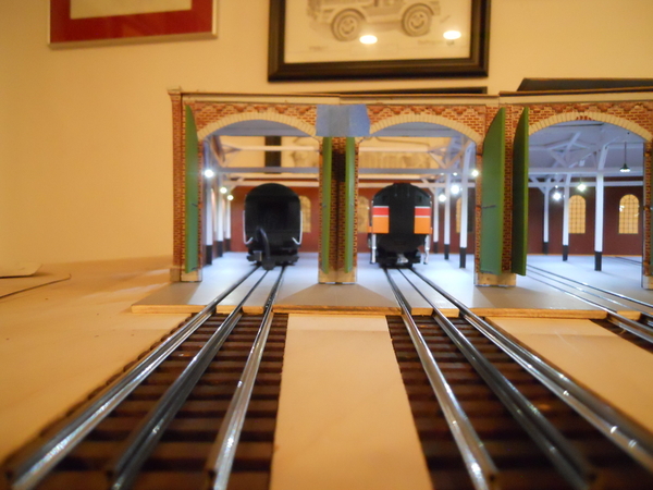
I have lots of room between the structure and the tops of the engines. I did receive my Altoona smoke jacks yesterday. I think there may be a need to do some trimming (length wise) to get them to fit since they're designed for another structure.
Until next time...


Like the idea of the lexan roof however, I’m wondering if you couldn’t place a couple 1 oz weights into a rooftop mounted air handler??? Maybe that will be just enough to weigh the roof down to lay flat??? Love your progress!
Thanks for the update. I’m just starting a 320 build myself. I also plan on using a plywood roof. I fully anticipate having to use “rafter” supports glued to the underside to make the panels lay flat. I am also considering the AMW vents and smoke jacks. Looking forward to seeing your progress with those
@Scott R posted:Thanks for the update. I’m just starting a 320 build myself. I also plan on using a plywood roof. I fully anticipate having to use “rafter” supports glued to the underside to make the panels lay flat. I am also considering the AMW vents and smoke jacks. Looking forward to seeing your progress with those
If I continue with the plywood, I will also have to use supports underneath. I tried one and got it slightly out of place and had to peal it off. May try again if I don't do the lexan.
@LT1Poncho posted:Like the idea of the lexan roof however, I’m wondering if you couldn’t place a couple 1 oz weights into a rooftop mounted air handler??? Maybe that will be just enough to weigh the roof down to lay flat??? Love your progress!
Don't believe that'll work. The plywood lifts up on the edges. But I will look at it. Thanks for the suggestion.
If I have a next layout, I am 100% getting a turntable. I absolutely love the open top.
I have seen some threads that discuss purpose, and candidly, I'm a looper but the thought of bringing an engine out of the shed to run, seems pretty cool.
Another thread talked about showcasing various engines. Ok, I would be guilty of that. Show the newest / coolest, and easiest to run.
Looking great!
@Rich883 posted:Looking great!
Thank you!
Started messing with my smoke Jacks. Not all the chimneys are the same. There will be some trimming involved to get them that way. I had to increase the angle of the flu so it would sit plumb on the roof. I'm still using my carboard roofs for any template work.
If you notice, the right flu is slightly longer than the left. The right flu is also the one I modified to sit plumb. The back side (left) was left alone and I removed about 1/16" on the front (right) side. I will make all the flu's the same length when I get all 5 completed.

This is the unmodified funnel clearance, but with the correct angle on the dangle.

I removed 1/8" from this funnel to give me a bit more clearance.

This is the modified funnel clearance. If I need to drop it down, there is enough funnel inside the flu to make that happen. But for right now, the funnels will be cut 1/8" shorter.

I found that about 4"x4" should almost center the smoke stack on the engine with the center of the flu.


I have no plan to glue the funnel to the flu. There is enough of a clearance fit that shouldn't be necessary. The only gluing will be the chimney cap. I won't be gluing the jack to the roof either. If something where to happen, it could move accordingly without causing any damage. Basically it'll just sit there. Each smoke jack will be fitted to each spur/bay individually, just so I can ensure it is centered on the center rail of the track.

Good Thursday Morning everyone,
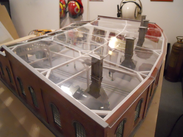
A quick update on the roundhouse. After trying to get the 1/32" plywood to lay flat, I decided to abandon that idea and go straight to the .080" clear acrylic roof. This is not my permanent solution. This would only be for when someone comes to visit and look the layout over. My ultiminate goal is the plywood roof with the simulated layed up roofing. I just need to find some thicker plywood that won't warp after it's been cut. The protective film is still on the acrylic, that's why is cloudly. I received the glue yesterday and will be gluing the panels together later this morning. I oops on the small #4 panel and had to remake it. That's why #5 isn't completed. The smoke jacks were moved inward towards the center of the roundhouse about 3/8", just to give the locos a bit more clearance to the back wall. I tried painting the jacks with a brush and it was a huge fail. The Scalecoat ll paint is thin and best sprayed with an airbrush. I'm waiting on a can of A.I.R. to arrive today to get those painted and detailed.
I'm not satisfied with the LED lighting setup I currently have. My plan now is to still use the current LEDs. But to do what Norm suggested and use the load resistors. That sure beats changing out the LEDs again...NOT! Time to sit down and figure out the resistance I'll need. Got 18 to do. I did purchase an adjustable walwart supply capable of 3v-12v @ 1.5 amps. I believe that should be enough to supply those 18 LEDs.

Until next time...
Very nice!
Peter
Thank you Peter!
Looking Good. What did you use to get a clean cut in the acrylic panels ?
@Dave_C posted:Looking Good. What did you use to get a clean cut in the acrylic panels ?
Used this... Watch the video thats attached with it. Multipule passes are necessary for a clean cut. It works great.
Not much going on with the roundhouse. I did manage to paint the smoke jacks and get them somewhat detailed. I hooked up my Cab 1 and put my CSS on the track to the right bay. The track is a bit dirty, but it worked as advertised. It's hard to see the smoke coming out of the chimney due to all of the glare but it's there. I have some Lunan 1/8" plywood for the roof on order, hopefully that will lay flat.


Chris, I purchased some kits at a divorce sale many years ago. One of those was a old Korber 320 Roundhouse kits. The kit is probably 20 plus years old. Someone started it only to the point of slopping on paint to the parts. I'm now trying to remove the paint so I can start fresh. Two of the fronts are warped and one of the side walls. I've hunted for replacements but haven't found any. I did contact Mr. Muffins and they also said they don't stock pieces. You state you heated yours in the oven. Can I ask for more details? Did you put on a flat sheet? For how long? Did you add weight to it while it was heating and cooling? Did you add anymore structural support to the fronts after straightening them? I do have the typed 4 pages of instructions but nothing else. As you stated those old instructions aren't very useful. I'm downloading some of your pictures as reference material. I'm enjoying following along on your build. It looks terrific so far. Thank you for any suggestions you might have! John
Good Morning John,
Okay, I did a search on the web and a guy with the same issue popped up and I followed what he had done, but with a few small exceptions. I started off using a cookie sheet, that didn't work 'cause it was too flimsy. Then I used a cast iron griddle, a much more solid surface flat surface. I placed the parts and griddle in the oven, cold. Set the oven to 250* and preheat. Let it warm up, Then turn off the oven when it's preheated (DONT LET IT SIT IN THE OVEN @ 250*) and let it cool completely, leaving it in the oven with the door closed. Don't remove it until its completely cool. This is going to stink, turn on your hood vent fan.
The key is slowly heating it up, and slowly cooling it. 250* wont melt anything, just softens it. This is why you dont move it from the oven. Just let it cool. LOTS OF PATIENTS! This takes time. NO weight of any kind is necessary. Once they're flat and cool, store them on a hard flat surface until your ready for them. Dont put them back in the box. Painting and weathering can be done at this time.
I used superglue to glue the panels together. I didn't sand the sides smooth, I should have.
You have the plans for the framing? If not, I got them still. All of the cross bracing has to be cut to length. So sanding the sides would be okay. Just need to be sure you get everything equal.
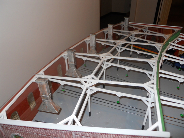
I added, lots of 45* bracing to my wood framing as shown above. Making it look more prototypical and structural. When you build the framing, use a small square or a speed square to get the proper angles. You will only have enough wood for the planned framing. I got a 1/4" x 2" x 3' piece of poplar and ripped that down to 1/4" square strips. This is what I used for the 45s and all the cross bracing. I used wood glue for the framing. Put wax paper under your framing so it doesnt stick to the framing plans. (old balsa wood plane building trick) Use lots of T-pins to hold the wood pieces in place until the glue dries.
I then sanded everything with a palm sander using 320 grit paper.
Good luck, ask any questions. I'm on here every morning, lurking.
Forgot...One last thing, use something that's long enough and straight to use for the "roundhouse floor". Like a metal yard stick. Butt all of the columns of the framing to this. This ensures the framing will sit on the floor evenly. Ask me how I know....Found out the hard way.
A quick update on the roundhouse since it's been almost 9 months since I posted any progress on it. I took Norms suggestion and got a dedicated power supply at 12 volts, bought 750 ohm resistors, and placed everything under the roundhouse. So each LED has its own load resistor. I did the buss bar thingy using 14 ga copper wire and gluing that to the bottom of the roundhouse floor.
I glued all the panels in place finally. So it's now complete, structrally. Now, it's getting the layout built and placing the round house in it's position. Pictures will follow at a later time, due to logistical issues.
Until next time...
Access to this requires an OGR Forum Supporting Membership


