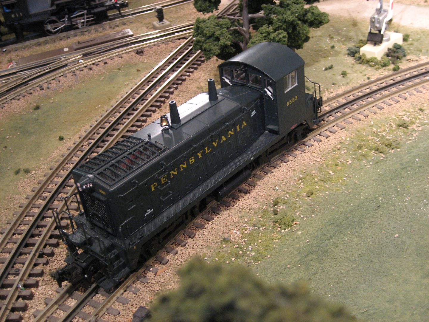
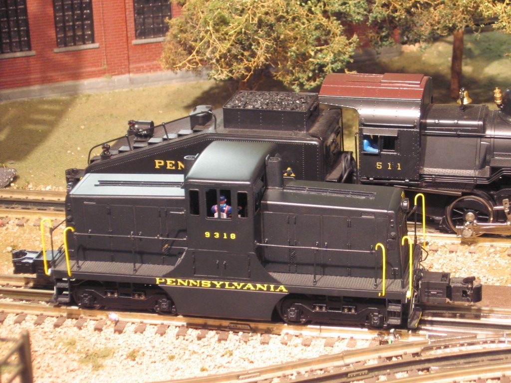
I'm looking to add a post war switcher for my freight yard. I have a few magnetic uncoupler sections but not everywhere. 

Were there any switchers that were built from the factory to uncouple on the whistle command? I know there were some pre war that were built like this, even some built to reverse on the whistle command and uncouple on the directional power drop off. 

I'm thinking a NW-2 would work great but would be open to a steam unit to. I know the 1656 steam switcher is desirable for its low gearing but not sure if it has the feature I want. 

Is it a hard conversion to make a coil coupler work on a whistle relay? I am thinking a 624 there are some on eBay with seasoned body shells and no bell or whistle feature to give up in a conversion. 

Original Post

Replies sorted oldest to newest

I do not think there were any post war locomotive with remote uncoupling. There is a family of prewar switchers with this feature, but converting the couplers can require some experience and the right tools.  These is a rather long thread on this board about the prewar 227 series of switchers that has some detail. You would need to find a post war switcher with electromagnetic couplers and a whistle or horn relay. There are normally accessory shoes on each each truck of the loco.  The shoe is connected to one end of the coupler coil.  There other end of the coil is ties to the truck frame which goes back to common through the wheels.  When power is applied to the accessory shoe the coupler opens.  On some locomotives the accessories shoes are ties together electrically. If either accessory shoe is energized, both couplers open. To make remote uncoupling the horn needs to be disconnected from the whistle relay, which has just one contact. Apply power to one side of that contact and connect the other side of the couplers or accessory shoe.  When the whistle relay is energized the coupler coils are powered and the couplers open. Many of the horn relays connect the horn to common rather than power. If this is the arrangement you have, the relay will have to be isolated from the loco frame and connected to power. This is already done on several locos by Lionel, so just look for an example. 

I believe the 623 may be a good candidate for this conversion.  There are not many switchers that are because Lionel changed most of the switchers over to thumb tack couplers early.  I do not believe there are any post war steam switchers with whistle relays.

David is correct, there is no post war steam switcher with a remote uncoupling feature, one of my projects that got put on the back burner is a 1615 switcher I want to do the same type of conversion. the rear truck on the tender is obviously a no brainer wiring it to the relay. I found a MTH coil coupler that is the right length for the front, and looks like almost a drop in part, but I have not made the swap as of yet. I have the part number at home and will post it up here when I get home from work. my plan is to mount a whistle relay in the tender shell, and just have a single wire between the loco and tender......thanks for the post, I think this weekend I will get this switcher off the back burner!   

Tug_Driver posted:

I will look into that seaboard switcher. How does a whistle relay get wired? Do the wires for the coil just pick up the center rail and wheel common and the activation of a whistle switch on a transformer do the rest?

i figured that any coil coupler locomotive could be used in this kind of conversion. 

Yes, the whistle relay coil just connects to the center rail roller and the loco frame, which is common. If the transformer has not been modified with a diode, it takes a little current to get the old style rectifiers to work.  So you may need to have a couple of lighted cabooses or something else with lights to add a little load to get the whistle relay to work. The whistle controller on the transformer has two steps. First one puts out about 5 volts DC and the second one holds the relay closed with a little over a volt. If you have trouble with the whistle relay, put a DC volt meter across the rails and see how much DC voltage is getting to the locomotive. Clean wheels and rails are also important. 

ADCX Rob posted:

TELEDYNE

Thanks for the wiring diagram. It seems as simple as I thought it could be. It's amazing that ac power passes through the whistle relay all the time but doesn't close it. I will be running a KW and LW phased on this layout. The KW was rebuilt before I bought it and has a stud diode. The LW was also services but does not have a diode so we will have to see how it works. 

Does the whistle relay frame make the ground to the chassis or is it a separate wire?

Mikado 4501 posted:

I have done this conversion on the Seaboard 6250 NW-2. It's very easy, and is a lot of fun. The whistle relay usually only costs $20. You just have to make sure the relay is insulated from the ground in the locomotive frame. The contact tab on the relay gets soldered to the electrocouplers line.

Could you elaborate on the insulation and the contacts?

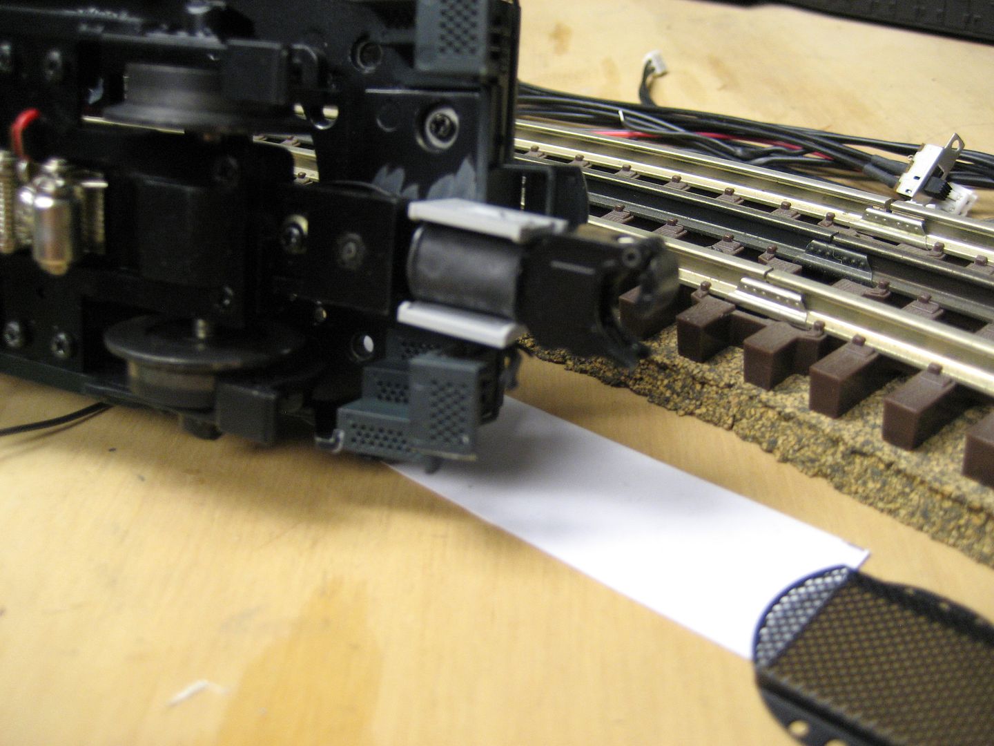
i have the relay mounted in a 624. The tab on the top I could insulate from the mounting frame I made with some thin fiber paper and over size the hole to make sure the screw doesn’t touch on the way through but would I then have to remove the end of the coil wire and connect it to the chassis separately for the coil ground and then have a “live” relay frame?


Attachments

Images (2)
  • 94726692-09F6-4F63-9F9C-FB5E9368DBB3
  • CBE65BD4-0238-45C6-8BDD-DC0D8C698880

Similar electro-couplers used for Lionel and Lionel TMCC conversions operate at a higher voltage.  Most of the ERR and other TMCC conversions provided access to couplers.  There were different lengths of couplers for the different conversions.    This is an older Atlas SW9 that I upgraded, it did not have electro-couplers.  Atlas is another source for coupler parts.  Pictured is an Atlas articulated coupler, that flexes/pivots, two points, which allows better operation on tight curves.

I had used part of an Atlas coupler on a Rich Yoder 44 tonner.  The frame mounting of the existing coupler and unusual drive system made electro-couplers on this small switcher model difficult.

Note the length of the coupler beyond the model.  The small plastic sleeve over the coupler electro-coil is an Atlas part.

The mechanical thumbtack coupler was shorter.


Last edited by Mike CT

Michael,

If you go to the All Gauge Toy Train Association web page, (www.AGTTA.com) and look in the Tech Tip tab for Teck tip #2, or the Newletter link for the April 2010 newsletter, there is a Tech Tip article on how to mount and add the relay.  In the article a metal bracket is used to attach the relay to the other side of the E-Unit mount.  Take a look, it might be the info you need.

Ross


Last edited by Ross

Add Reply

Post

OGR Publishing, Inc., 1310 Eastside Centre Ct, Ste 6, Mountain Home, AR 72653
800-980-OGRR (6477)
www.ogaugerr.com

×
×
×
×
Link copied to your clipboard.
×
×