I'm expanding my existing layout and need to organize my wiring and power supply / DCS system as well. I'd like to centrally locate everything. I'm looking for suggestion / ideas on control center folks have built in the past.
Thanks,
BC
|


|
I'm expanding my existing layout and need to organize my wiring and power supply / DCS system as well. I'd like to centrally locate everything. I'm looking for suggestion / ideas on control center folks have built in the past.
Thanks,
BC
Replies sorted oldest to newest
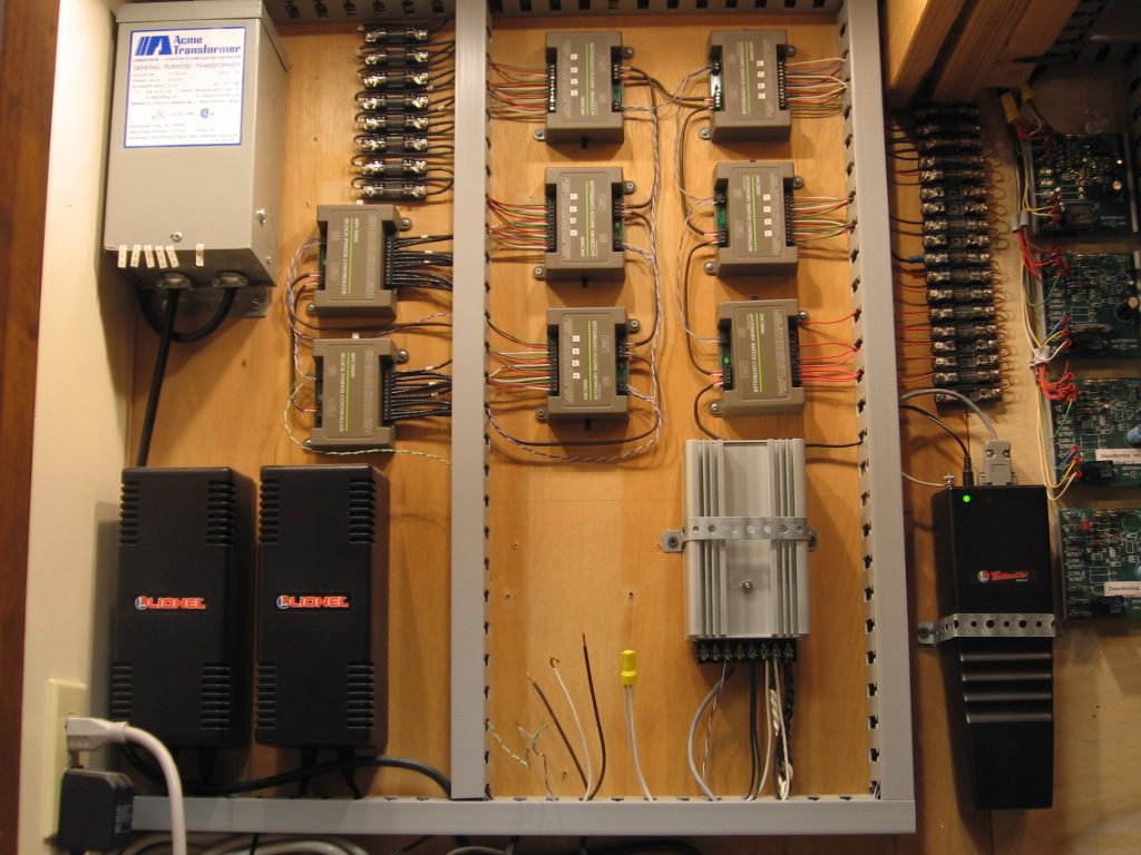
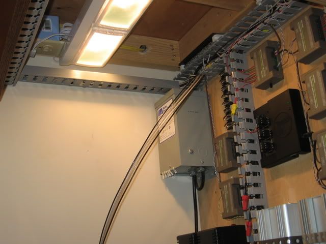
Far right section is Atlas 6924 relay boards (21) boards controlling (25) switches.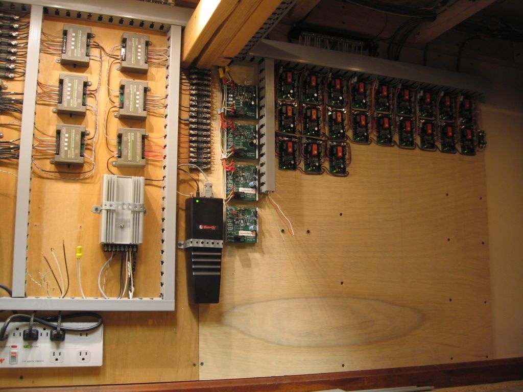
The layout is above. Wires are in the grey wire tray. The only control above the layout is a 110 volt off/on switch and two Cab-1's.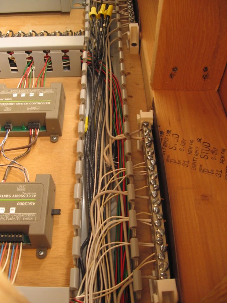
Thanks again Mike. These pictures are excellent. Is the portion under your layout where all of the power center is located enclosed? If so, how do you access? Do you have any other tips to make my wiring efforts neat and organized. Before now I secured everything with a staple gun.
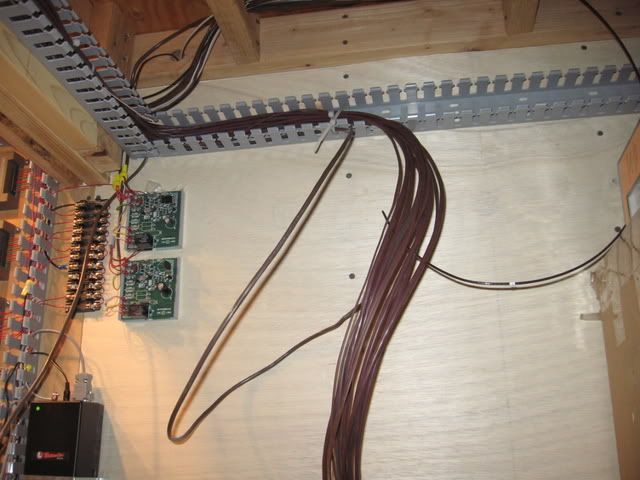
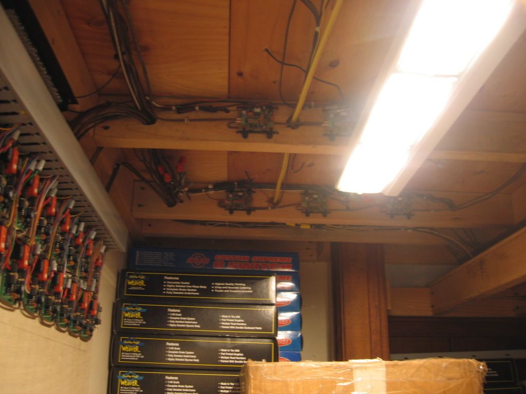
Thanks again Mike. These pictures are excellent. You're welcome.![]() Is the portion under your layout where all of the power center is located enclosed? Everything is under the layout in one area, it is not enclosed, easily accessible. If so, how do you access? The area is lighted and near the edge of the layout. I can access the area on my knees. I have spent some time sitting on a small box. My wife says I sleep under the layout. Do you have any other tips to make my wiring efforts neat and organized. I made a living as an electrician, but grossly underestimated the number of wires required. There was some rip-out and re-do of the grey wire tray. Before now I secured everything with a staple gun. I use a lot of plastic romex staples and cable ties. The two layout rooms are 23ft X 15 ft average, a relatively small layout.
Is the portion under your layout where all of the power center is located enclosed? Everything is under the layout in one area, it is not enclosed, easily accessible. If so, how do you access? The area is lighted and near the edge of the layout. I can access the area on my knees. I have spent some time sitting on a small box. My wife says I sleep under the layout. Do you have any other tips to make my wiring efforts neat and organized. I made a living as an electrician, but grossly underestimated the number of wires required. There was some rip-out and re-do of the grey wire tray. Before now I secured everything with a staple gun. I use a lot of plastic romex staples and cable ties. The two layout rooms are 23ft X 15 ft average, a relatively small layout.
![]() The power center MikeCT has makes all kinds of sense if your topside space is limited as mine is on this current 9x16 attic layout. I just have Cab 1s, a track schematic with 15 turnout toggles and panel meters up above.
The power center MikeCT has makes all kinds of sense if your topside space is limited as mine is on this current 9x16 attic layout. I just have Cab 1s, a track schematic with 15 turnout toggles and panel meters up above.
The first time I used this concept was in 1992 for powering a high shelf operation in the 18' high Kitchen of our mountain cottage when my wife ran me off the breakfast bar top. I had pwZWs, Power Programmers,etc, mounted on a covering, framed plywood surface under the overhang of the cabinet bartop with flexible conduit running up the wall to feed 7'-6" and 9-'0"high shelves[5 tracks 14x28]. Not ideal for operating ZW throttles but worked until TMCC came along. [She had deeded me the upper area of the kitchen to get me off the carpet in the Den]![]() .
.
Blue Comet
As you requested, this 3 year old fuzzy photo shows my layout Power Center location near the room entrance. Note the blue flex conduit extended over the door frame to carry the railpower wiring bus and turnout wires to the layout side opposite the Power Center. I had just about completed a rough-in of the principal wire runs before covering with plywood. I prefer to do as much wiring as possible while standing upright.![]()
photo: marking the radius on the grid edge. The Sharpie is marking thru a hole at the 43" mark because the pivot point to swing the radi is a hole at the 1" mark--my "holy" tape! 42"=084, note red 072 inside it.
Post below---topside schematic showing turnout toggles, panel meters and Power Guards. Simplified turnout operation--the direction the toggle handle leans on the schematic indicates the actual position of the turnout,i.e; whether "thru" on the mainline or "out" on a siding or spur.
The top row is AC Volt Meters and bottom row is Amp meters. Meter on the top right is a DC Volt Meter monitoring the 12 volts for the turnout circuit.
Green "bug-eyed" lighted boxes are PowerGuards. Red light flashes upon spikes, which minor ones happen frequently.
Hide A- Wire, Inc's number: 215-856-4547
I haven't used them is a long while so I don't know the product line.
Graybar Supply, Automotive and Industrial Fastners,Grainger and others used to carry the trays .
Search under wiring duct. . http://www.grainger.com/Graing...uct-1GUP6?Pid=search Click on the link to access.
There are different sizes and covers.
Access to this requires an OGR Forum Supporting Membership
