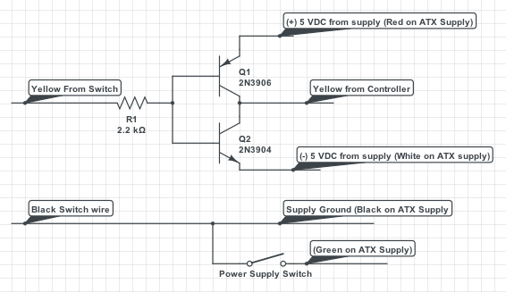
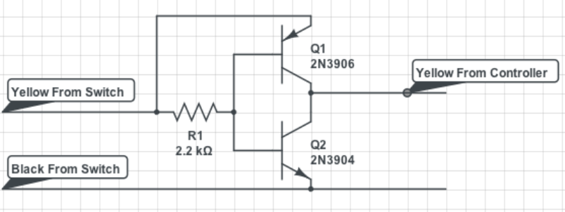
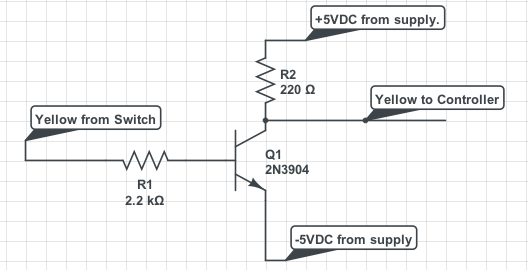
It seems my assumption was a bit off, a +5/-5 swing actually makes more sense. I was counting on the swing of the AC to do the reversing of polarity on the common side. Turns out my head wasn't screwed on right in the previous diagram anyway as the +5 had no supply.
It seems like reversing the internals of the switch may just be the simplest solution, as it should also reverse the indicator on the switch it's self.
As far as only inverting the lights on the controller, and not changing anything inside either part, the 2 transistor method will still work, you just need a +5/-5 supply voltage. Now you could go about building one, but that is a big pain in the you know what. You can also buy negative 5 volt converter boards for 5-8 dollars on the auction site. Add a couple dollars for the positive 5 module, and be good to go. My solution is to use a power supply from a junk computer. Any power supply from any PC made in the last 20 years will do, though a brand new el-cheapo $15 one will also work. You also get a 15 AMP 12VDC circuit you can use for lighting or accessories, and a 30+ amp 5VDC line that can power any electronic wizardry you may want to run. We also get the -5V line for the switch controller lights. It's worth noting it's only a half amp, so you can only drive maybe 5-10 switch controllers off it. if you got a bunch, building your own supply may be easier.
Anyway the circuit is mostly the same, with added external power supply.

I think this one will actually work, but have prepared for failure. Is there such a thing as a rusty brown star?
JGL
Edit, a flaw has been pointed out to me off-forum, and it seems as shown the circuit will not work. I'm thinking the flaw could be fixed with a pair of diodes, one on each transistor's base, but, I'm not sure about that yet... Think I might have to start from scratch on this one...


