Can someone explain to me how they get wired. I understand that each port carries power but where does the main power connect? Thank you.
Replies sorted oldest to newest
The main power comes in wherever you'd like to put it. If you'd like to only have one power (or ground) feed coming in, you need to make jumpers to connect each post to the next. They sell strips of metal that do this, but it's easy to make your own.
In the picture I have power (red) coming in on the left. The jumpers at the top make the left three posts power. Conversely, the white wire coming in on the right is my ground, and the jumpers make the three posts on the right all ground.
Attachments
So I thought one side can be hot and one side can be ground. However, you have it across from one another?
As delivered, these types of terminal strips are only connected electrically to the port directly above it, not any other ones to the right or left. Having the entire top row hot, and the bottom row ground wouldn't work.
TrainHead: There is a Terminal Block made by MTH that gives positives and negatives on alternate sides of the board. It's set up on a circuit board that makes the appropriate connections. The one shown in your picture above simply passes a connection from one side to the other side; as in connect one wire to another. As mentioned, you can make up whatever connections you want using jumper wires or metal connectors.

Attachments
I just ordered 10 of the 8 terminal ones from Mouser, 1.38 each , best price that I could find, everyone else wants 4-5 bucks each.. Mouser part# 538-MS8141 the pic they show is a 4 terminal one just for reference..https://www.mouser.com/ProductDetail/Cinch/MS-8-141/?qs=e4mSxZDfAPacpPxA6Trcxw%3D%3D
Jeff
Attachments
CMB4 from Allied Electronics with internal jumper is your best bet. One for red and another for black. I used the CMB4-10 which allowed me to connect one port to the transformer and 19 to the track.
Attachments
@jmiller320 posted:CMB4 from Allied Electronics with internal jumper is your best bet. One for red and another for black. I used the CMB4-10 which allowed me to connect one port to the transformer and 19 to the track.
jmiller320 please show me your wiring of this block. Thank you!
The CMB 4-10 has an internal jumper that is sold separately. The wiring is pretty straight forward. I connected a red wire to the Track one port on the Z4000 for the outside loop. I connected this wire to a quick blow 5amp push button circuit breaker. I ran a red wire from the circuit breaker to one of the ports on the CMB4-10. From the CMB4-10 I ran a red wire to a Fastrack section and attached a crimp on connector and attached it to the center tab on the track. I continued this another 18 times and connected another CMB4-10 and continued the process around my layout connecting 18 more track pieces and a third CMB4-10 to complete the loop. I did the same with the black wire with the exception of connecting to a circuit breaker. I did the same for the the track 2 ports for the inside loop. The CMB4-10 is about 1" X 1" X 3". The internal jumper is sold separately and has to be installed by the user. The photo I attached above only shows one side, the other side is the same. My wiring is a little messy, I was working alone when I ran the wires from the track to the underside and had a little extra. These pictures show the inside loop.
Attachments
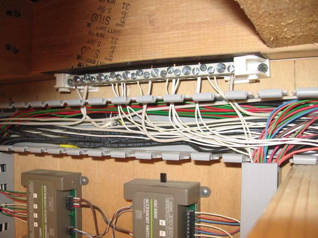
Can be purchased at the big box stores. Works well for all commons, both track and accessory. Electrical panel neutral bars.

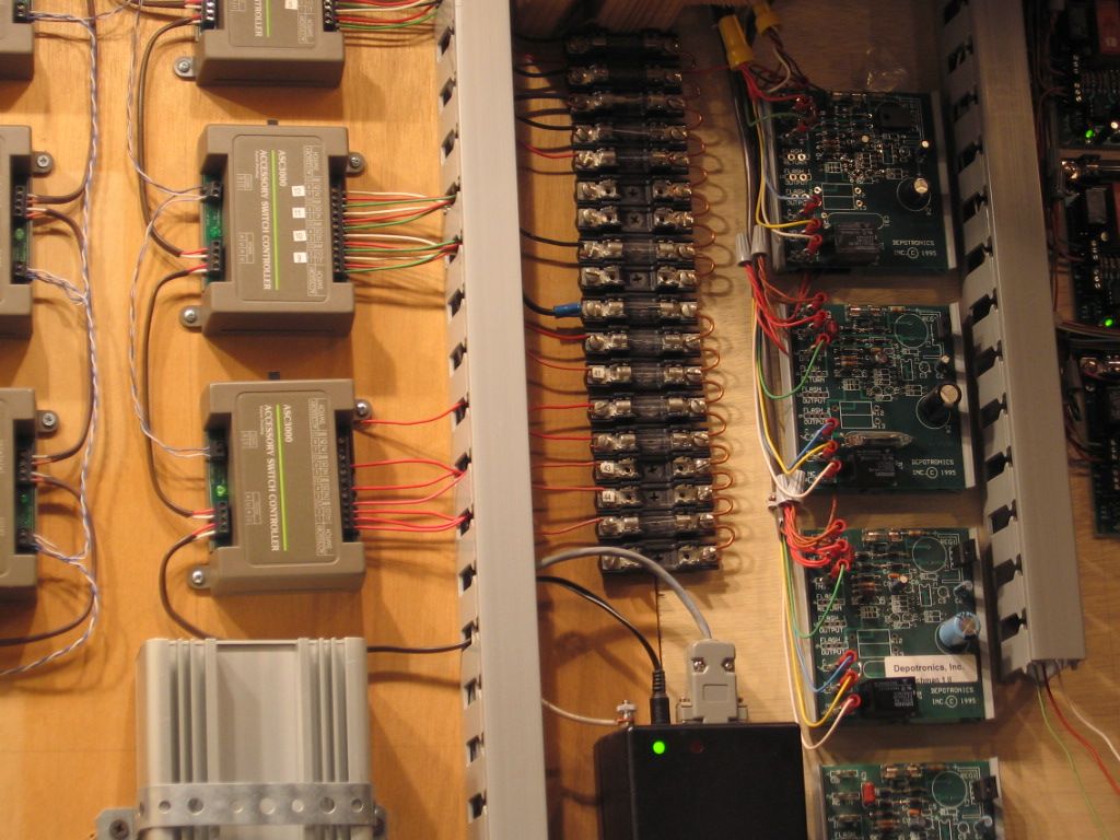
Accessory Power wires a little different approach with fuses.

I have a well-stocked electronic junk box. So I use barrier strips and plastic or metal project boxes from the junk box to house two barrier strips per box, one strip per block. I use un-insulated wire to link all the screws on one side of some barrier strips--see pic. Then the center rail of each track section is wired to the other barrier strip terminals.
In the gray box pictured, a different kind of barrier strip is used--the terminals are all soldered together on the back of the strip while the screws on the front connect to each track section.
The boxes are mounted facing out at the edge of the layout close to the blocks that get power from them. This way I never need to crawl under the layout. The track feeders drop down from the track, through the benchwork, and out to the closest barrier strip box.
The feeder drops from my outside rails are all simply soldered together at a point where they connect to the wire from the TIU using old terminal strips from the junk box. Usually, these terminal strips are mounted on the outside of the plastic boxes.
If I didn't have a good junk box, I'd be using those electrical panel neutral bars--those are a great idea.


