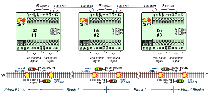
Remember, the #1 goal was not expensive!  I'm afraid if we get into daisy chaining signals and all the complexity that involves, we'll defeat the whole purpose of the project. It this whole project ends up costing more than around $10 total for a board, I'm afraid it's not going to go very far.
After all, Azatrax has one that does all this and also handles signals in two directions for $40 for each board.

Problem is these use IR, not insulated rail. But like the Atlas controls, would it be hard to have two inputs to the circuit board. One will engage the red light (Current block.) and the next would engage the yellow light (Following block.)? If neither has an input, then the light would be green. So you would need two sets of boards, one for each direction, which is how Atlas handled it. And if the boards are low cost kits, I would not mind having two sets, one for each direction of travel. With that said, you could make it a simple trigger and it's up to us if we attach it to the current block's red light, or the previous block's yellow light. That would give two boards in each direction, so 4 for one block. But as pointed out here, the low cost signals use a common, so two lights can't be powered at once.
How I'd like the board to be is have two inputs (Via isolated rails.), 3 outputs (Red, yellow, green), and power input. Input 1 is the current block, and Input 2 comes from the following block. When the board is powered on, it shows green. When a train entered the block, triggering Input 1, the light goes red. When the train enters the following block the board is triggered on Input 1 and 2, but still shows red due to Input 1 still triggered. Once Input 1 is no longer triggered the light goes to yellow as it is still triggered on Input 2. Once no longer being triggered on Input 2 the light goes back to green. Perhaps instead of calling it Input 2, it could be Input from following signal. Then you can have another output on the board, Output to preceding signal, which really is just a pass through for Input 1.
So the logic of the board is I is the Inputs, and on is triggered and off is not triggered:
I1 off, I2 off then show green.
I1 on, I2 off then show red.
I1 on, I2 on then show red.
I1 off, I2 on then show yellow.
But like John says, it's not as easy as someone else doing it, and I'm a mechanical engineer not an electrical engineer.
![]()


