I purchased one of these timer relays to try out for non-derailing operation of my Atlas switches. The module is powered by 12v DC and the relay is rated for 8 amps at 120 VAC. The timer can be set to energize the NO post of the relay for a specific period (I plan to use 1 second to protect the switch motors) and then remove power. Does anyone see a problem with powering the module directly from a bridge rectifier that is connected to an insulated rail and the 14v accessory power post of my z4000?

Image result for altronix 6062 timer

Altronix Timer Relay

Attachments

Images (1)
  • Timer Relay
Original Post

Replies sorted oldest to newest

Besides the bridge rectifier you will also need a capacitor to filter the power into a reasonably pure DC source.  Without the cap the power will still be turning on and off 120 times each second.  

In addition, when you convert to DC you will get a higher voltage.  a 14 VAC pure sine wave input will produce almost 20 volts DC.  (19.7)  also, if you are using a modern transformer with a power brick and separate controller for the throttle, a so-called "chopped wave transformer", chances are the DC converter will have an output close to 25 VDC, even with the throttle turned down.  

If the relay board will handle 20+ volts, you'e all set.  If it won't, you may want to look at a variable AC to DC buck converter module.  These can be had for just a couple bucks on the auction site.  

JGL

JGL,

Thanks for the information. My transformer also has a 10 volt post, so that might get me closer to what I need. I didn't know about the need for a capacitor to smooth the current.  What size capacitor should I use?

Mike,

That's good news. I have several switches, so I will probably try the Altronix relay for a few of them and then decide which I like best.

It really depends on what the current draw is for the board.  I'm going to guess that anything from 1000-4700uF will do the job just fine here.  Also make sure the cap is rated for enough voltage.  There are various sites that offer calculators and better explanations than I can offer, if you want to get an optimum value.  

JGL

I just want to update everyone on my results. I put together a test circuit and everything went well. I connected the 10v posts of my z4000 to a bridge rectifier, which produced an output DC current of about 12.3 volts. I connected a 2200 microfarad capacitor across the output to smooth my current. The timer relay module worked perfectly when connected. I did notice that the module took 2 or 3 seconds to reset after I turned off power because of the current bleeding from the capacitor.

When I do the math on costs, this solution is more expensive than the Atlas 6924 board. I spent about $20, but the board only controls one leg of a turnout. The Atlas board controls both legs and also can be used for power routing. I have one turnout that is a little rough when cars go through in the wrong direction, so I will probably use the Altronix board for that and wait for the Atlas boards for the rest of my turnouts.

Thanks for your advice.

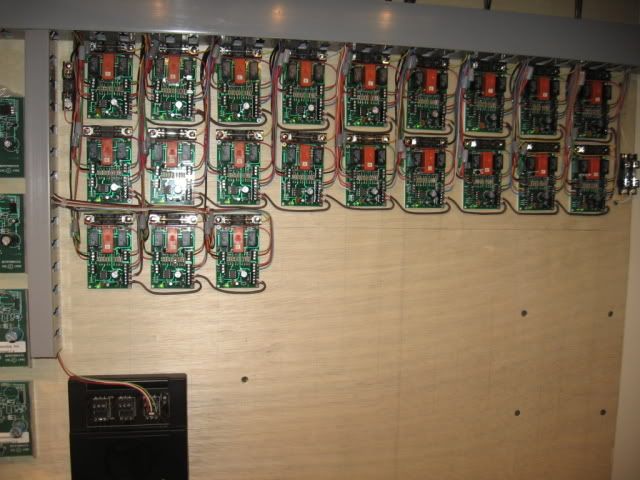
It's been awhile since I installed these 6924 relay boards.   They seem to have solve a lot of problems, IMO.  21 relay boards operate 26 switches. There are (5) cross-over paired switches, (1) 6924 controls (2) switches.  

Note that (1) 6924 controlling two paired cross over switches is also a savings.  There are also (2) sets of NC/NO contacts available on each 6924 board for power routing multiple track circuits or operating  other track side accessories used.

Best wishes with your project,

Mike CT.


Last edited by Mike CT

JohnF, 

Earlier in the thread I took the question as 'this is the board I have, what do I need to power it?'  and it sounds like that has worked out, but turns out not to be very cost effective.  It may be there is another choice of board you could go with, however if cost savings is what you're after.  I'm unsure what the cost of the timer-relay board you used is, but I'm confident that I could come up with a set up that does the same thing for less than $5 per relay including the power supply... likely much less if you combined parts for multiple switches.  

If that's something you'd like to look into, let me know.  

JGL

JGL,

My big expense was the timer relay board ($16). I would be interested in more details about a less expensive solution. I was a little overwhelmed when I started searching the internet for timer relay boards. Many of the boards had instructions that were unclear, and I was not sure if they would work for me.

You were right about my initial question. I had never used a bridge rectifier before, and I wanted to make sure that I wasn't doing something wrong. I'm glad I asked because I didn't know about the voltage increase and the use of a capacitor.

Mike,

Nice picture of your Atlas relay boards. I need to work on making my wiring a little neater.

JOHNF, 

There will be some trade off between easy to use and low cost here.  Note that the complex stuff only has to be done one time, and I'm perfectly willing to take as much time as is needed to make it understandable if needed.  

I do want to make sure I fully understand the purpose of this board and how it is supposed to work.  It seems the idea is to make sure that the coil on the switch machine turns off after a couple seconds, even if an engine/car is parked on the isolated section of a switch for it's non-derail feature.  

As a side question, is this auto-shut-off wanted, or needed, when throwing the switch from remote control?  ex. to prevent damage from someone holding the button down too long, or from a signal remaining turned on on something like a DCS AIU?  

The next question would be how many such switches do you have that need the auto-shut-off/ anti-derail function? 

Is it acceptable to have one control module in a central location to run all the switches, or would it be most convenient to have a separate unit for each switch?  Or is it possible to have a couple units spread about the layout where each could control several near-by switches?  

Costs and ease of assembly will vary quite a bit depending on what options work for you, for example, a controller capable of operating 8 switches should cost about $20, where as a single switch controller would cost about $8 in parts.  

Of course with the option of running one main control board you'll have to factor in the cost of running wires to each switch from the control board.  If you already have wires for remote control, however, these can be shared for the switch machines, and you can use very small gauge wire for the signal lines for anti-derail.  

As a side option, with the method I'm thinking of, if you run TMCC you could add TMCC control of your switches for only a couple dollars extra.  

Anyway, As I said, I'm happy to put in the time if it sounds like a good idea. I enjoy spending my free time piecing together circuits and such like this.   If using the options that are already commercially available seems simpler, or less of a head ache, though, go that way.  

JGL
Johngaltline@comcast.net


JGL,

Thanks so much for your help. I enjoy these types of projects, so let's give it a try. Here are my goals with this project:

1) The main purpose is to turn off current from isolated rails to protect the coil on the switch machines.

2) The only other way that I am going to throw the switches is with a momentary switch, and I do not need protection for these. I don't plan to use an AIU or TMCC.

3) Cost is not a big factor, so I'm willing to spend extra for reliability/ease of use.

4) I have 3 groups of switches - 16 in a yard area, 10 leading to/from the yard area, and 28 on the rest of the layout. It would be best to have 2 separate modules to control the non-derail operation. One for the 28 on the main part of the layout, and another for the yard and the area leading to the yard. I also plan to use momentary switches to control all turnouts. I plan to have one control panel in the yard area for the 16 switches there and the 10 leading to/from the yard. I will have another control panel for the main part of the layout. I will use this to control the 28 switches on the main part of the layout. I would also like to have a 2nd set of controls for the 10 switches leading to/from the yard on this panel.

Let me know if you need any more information.

John

Would seem an Arduino or similar reading inputs from derail rails could then output to the switch motor coil an x long pulse.  Might even be able to program longer pulses for balky motors.  Or set up so that on layout power up, motors snap to preset positions, assuming a car is not sitting on a derail rail. And if desired, after a preset, board outputs turnout position status to LEDs (of course if switch is manually changed then LED correspondence is meaningless until a train or button push resets motor and its LED correct.)

Seems like Bruce Chubb system would do the trick, except you need to have a PC running to operate, whereas an Arduino could be a stand alone "low level tasking system"  and immediately running without waiting for a PC to load programs etc.

Just an idea.

rrman posted:

Would seem an Arduino or similar reading inputs from derail rails could then output to the switch motor coil an x long pulse.  Might even be able to program longer pulses for balky motors.  Or set up so that on layout power up, motors snap to preset positions, assuming a car is not sitting on a derail rail. And if desired, after a preset, board outputs turnout position status to LEDs (of course if switch is manually changed then LED correspondence is meaningless until a train or button push resets motor and its LED correct.)

Seems like Bruce Chubb system would do the trick, except you need to have a PC running to operate, whereas an Arduino could be a stand alone "low level tasking system"  and immediately running without waiting for a PC to load programs etc.

Just an idea.

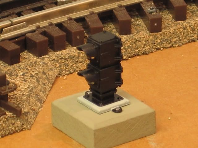
Interesting to note that the Atlas 6924 relay board has the ability to add indication lighting with (2) sets of NC/NO relays.   In addition to the board relay's, Atlas 6931 dwarf lights, are designed to be controlled from the input terminals of the snap switch motors. There is an additional PC board that requires power.   This indication method proved to be an advantage for me, even though I had already installed the 6924 relay boards.   Fabricated wood/concrete bases are not part of the 6931 dwarf light.  

Last edited by Mike CT
JohnGaltLine posted:

JOHNF, 

There will be some trade off between easy to use and low cost here.  Note that the complex stuff only has to be done one time, and I'm perfectly willing to take as much time as is needed to make it understandable if needed.  

I do want to make sure I fully understand the purpose of this board and how it is supposed to work.  It seems the idea is to make sure that the coil on the switch machine turns off after a couple seconds, even if an engine/car is parked on the isolated section of a switch for it's non-derail feature.  

As a side question, is this auto-shut-off wanted, or needed, when throwing the switch from remote control?  ex. to prevent damage from someone holding the button down too long, or from a signal remaining turned on on something like a DCS AIU?  Note:  I have all my switches are controlled with early model IC Controls, Accessory Switch Controllers.  When using the ASC's for snap switches,  they have to be programmed for momemtary, which you would think, would more, or less protect the snap switch motor from burn out.  Unfortunately, Hold the button a little tooooo long on the Handheld Cab 1 remote, and the ASC will cycle through more than one momentary, more than enough to fry a switch motor.   Experience this a couple time before I added the 6924 relay boards.   

The next question would be how many such switches do you have that need the auto-shut-off/ anti-derail function?   Best to do them all, It is interesting to note that the logic associated with a switched cross-over pairs , IMO, eliminates the need for both through and out non-derail inputs.   Enter a cross-over pair with the switch in de-rail would only apply to through in most cases.

Is it acceptable to have one control module in a central location to run all the switches, or would it be most convenient to have a separate unit for each switch?  Or is it possible to have a couple units spread about the layout where each could control several near-by switches?   Note:   Switched cross over pairs are controlled by (One) 6924 Atlas relay board.

Costs and ease of assembly will vary quite a bit depending on what options work for you, for example, a controller capable of operating 8 switches should cost about $20, where as a single switch controller would cost about $8 in parts.  

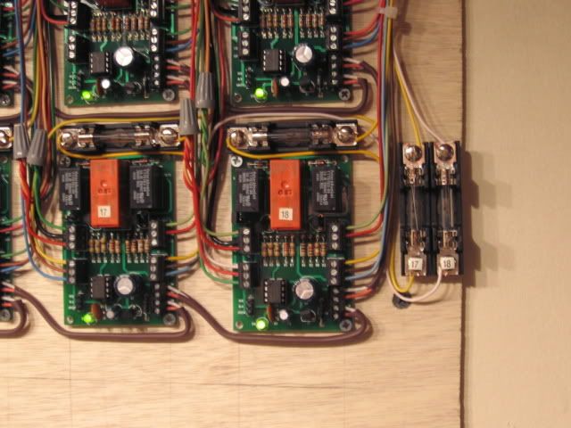
Of course with the option of running one main control board you'll have to factor in the cost of running wires to each switch from the control board.  If you already have wires for remote control, however, these can be shared for the switch machines, and you can use very small gauge wire for the signal lines for anti-derail.   Most case I was using and 18 ga, solid, (10) conductor thermostat cable from the Switch location to the central 6924 relay board location.  (10) or (13) conductor in most cases handle the indication for non-derail, and power routing as needed.  I eventually added a 3 amp fuse on track power input to the NC/NO relay used for power routing after a de-rail fried a board or two.  Note the fuse and fuse holder above each relay board.

Relay #18 :

Left side (6) terminals. Top down.

(1.) Green (through) common input Note: Gray twist nut combines Track rail/ASC.

(2.) Black  switch motor power input  Supplied from power system near the relay boards.

(3.) Red  (out) common input.   Note: Gray twist nut combines Track rail/ASC inputs.

(4.) White is track power input from switch location for power routing.

(5.) Red is power routing (through)

(6.) Green is power routing (out) .

Right side (6) terminals. Top down.

(7.) Green (through) switch motor power.  Relay board to switch motor terminal.

(8.) Red (out)  Switch motor power.  Relay board to switch motor terminal.  

(x) Switch motor common is not supplied from this board.

(9.) Yellow is track power input from switch location (2nd track circuit for a switch pair cross over.

(10.) Brown is power routing (through, 2nd track circuit).

(11.)  Blue is power routing (out, 2nd track circuit. )

As a side option, with the method I'm thinking of, if you run TMCC you could add TMCC control of your switches for only a couple dollars extra.  Can be done a couple of ways.   Additional input wiring from different devices, I used as mentioned ASC controllers. Which will handle (4) switches per controller.  Lionel SC-2's will do (6) switches.  

Anyway, As I said, I'm happy to put in the time if it sounds like a good idea. I enjoy spending my free time piecing together circuits and such like this.   If using the options that are already commercially available seems simpler, or less of a head ache, though, go that way.  

JGL
Johngaltline@comcast.net


Arduinos are interesting, but you do have to program them. They say it's kind of like C, but some of the programs are fairly simple. Lots of devices for them out there and many have sample code for them already written. Doing something more advanced or customizing for one's own use may take some study, at least it would for me. Some folks already know the programming end though, so it is probably much easier for them.

MikeCT,

One question on those atlas boards and signals, if you manually throw the switch, do the signals change, or do they only change when electrically thrown via button or anti-derail?  

Also On this comment: "Can be done a couple of ways.   Additional input wiring from different devices, I used as mentioned ASC controllers. Which will handle (4) switches per controller.  Lionel SC-2's will do (6) switches. "  My point was with the home built version, no SC-2's  are needed at all, saving quite a bit of cash, if one wanted control from a single hand-held remote.  

RRMAN, RTR12, and JohnF, 

Using Arduino was my plan, allowing the micro-controller to handle all of the timing.  In this case the program is pretty simple. boiling down to a routine that says "if input 1 is turned on, turn on output 1 ... but only for 2 seconds (or however long is needed.).  Then repeated for each switch input and output.  In this case I'm not particularly concerned about the program, or programing.  I'm willing to teach it if folks want to learn, but in this case I think it would be easiest for everyone for me just to write something that works.  I don't expect it to be all that complex.  

JohnF, Based on your reply above, it seems the best solution would be to have two controllers, one for the yard and yard area switches, and one for the rest of the layout.  the design of each of these controllers will be exactly the same, each one capable of running 32 switches.   (It would not be significantly more difficult to use 4 controllers for 16 switches each, if it would be easier to install that way)  

With the mention of having a second set of pushbuttons at the main control area for the yard, I think it useful to design this feature in from the start, and it can be done pretty easily with just 2 or 3 wires running from the main control panel to the yard.  If that seems like a good idea, the switch controller for the main panel will end up with a couple extra parts, but nothing much different, really.  

The design I have in mind will have 4 main parts. 1: A power supply for triggering anti-derail and push-button inputs.  2: An Input control board.  3:  A micro-controller (Arduino) to read inputs, send outputs, and provide the timing function.  4:  An Output control board to drive the switch machines.   for all of these there are many ways to get the job done, but I'm going to outline the way I would do it.  We can discuss other options if you like.  

1:  the power supply.  
To trigger the switches from isolated rails, it is very convent to add an additional DC power supply to the layout.  This supply would have it's ground side connected to the outer rail of the layout, using insulated rails to conduct signals back to the controller.  The + side of the supply is connected only to the controller unit, and the supply will have no effect on how the rest of the layout functions.  For this method to work, however, all the outside rails must be connected throughout the layout.  

2.  Input control:

Here wires from each isolated rail for the anti-derail as well as connections from the pushbuttons will come together in one place.  Each input will then have an opto-isolator to separate the layout from the controller, protecting from spikes and such.  From there the signals will be sent into parallel to serial shift registers.  I have the super common 74HC165 in mind, which will allow us to use only two or three pins on the Arduino for as many inputs as we want.  If this seems overly complex, don't worry, it's really not.  Think of this part like a toll booth plaza on a highway, 8 lanes of traffic merge into just 1 lane.  

3. Micro-controller:

A simple Arduino Uno or even less expensive Nano, will likely do the job just fine here.  the controller will be set up so that it constantly monitors all the inputs, and when it detects a train triggering anti-derail, or a manual button push to throw a switch, it will then turn on the correct output for a preset amount of time.  We could also add support for dwarf signals and the like if it is wanted.  it's not that hard once we're this far already.  

4:  Output.  
This part takes signals from the Arduino and sends them to the switch machines.  The first stage is the use of serial to parallel shift registers.  (74HC595) these work the opposite of the input side, allowing one output pin to be split up into many separate output channels.  From here the signal can be sent to relay board modules.  The most cost effective ones are the 16 relay boards, which would control 8 switches each if set up for the simplest wiring.  There are ways to wire things to get away with less relays, if that's something you'd like to discuss.  You could also use triacs instead of relays, but this would involve hand soldering the boards which could be tedious,  also folks around here seem to prefer relays for such things.  If wanted, provisions for dwarf signals, or panel indicators could also be added to the output stage, at very minimal cost.  

If this all seems like a lot, well, it is more complex than buying a ready made solution.  On the other hand, the heavy lifting here is still done with pre-built modules.  For construction, you could get away with using solderless bread board, though a soldered board would probably be preferred.  

I think I have enough parts on hand to build a demo of how this all would look, and I'll probably do that when I get out of work tonight, if nothing else just to show it is not nearly as complex as it sounds.  

One last question, what is the desired cut-off time for the switch machines?  This can be anything from 1/10th of a second up, so let me know what a good amount of time to insure the switch fully throws is.  

JGL

JGL,

Sounds like a great plan. My layout is wired for DCS, so all outside rails are connected.

I was thinking of using 1 second as the time. I'm guessing that it would be easy to increase the time for an individual switch if necessary. I would prefer to use 2 relays to control each switch to simplify the wiring. I would also like to add support for dwarf signals and panel indicator lights. 

John


JohnGaltLine posted:

MikeCT,

One question on those atlas boards and signals, if you manually throw the switch, do the signals change, or do they only change when electrically thrown via button or anti-derail?  The 6931 dwarf signals will change color when switched manually.  The Non-derail and power routing only works via the 6924 relay board.  the 6931 dwarf lights are not wired via the 6924 board but they can be, there are instructions.

Also On this comment: "Can be done a couple of ways.   Additional input wiring from different devices, I used as mentioned ASC controllers. Which will handle (4) switches per controller.  Lionel SC-2's will do (6) switches. "  My point was with the home built version, no SC-2's  are needed at all, saving quite a bit of cash, if one wanted control from a single hand-held remote.  

RRMAN, RTR12, and JohnF, 

Using Arduino was my plan, allowing the micro-controller to handle all of the timing.  In this case the program is pretty simple. boiling down to a routine that says "if input 1 is turned on, turn on output 1 ... but only for 2 seconds (or however long is needed.).  Then repeated for each switch input and output.  In this case I'm not particularly concerned about the program, or programing.  I'm willing to teach it if folks want to learn, but in this case I think it would be easiest for everyone for me just to write something that works.  I don't expect it to be all that complex.  

JohnF, Based on your reply above, it seems the best solution would be to have two controllers, one for the yard and yard area switches, and one for the rest of the layout.  the design of each of these controllers will be exactly the same, each one capable of running 32 switches.   (It would not be significantly more difficult to use 4 controllers for 16 switches each, if it would be easier to install that way)  

With the mention of having a second set of pushbuttons at the main control area for the yard, I think it useful to design this feature in from the start, and it can be done pretty easily with just 2 or 3 wires running from the main control panel to the yard.  If that seems like a good idea, the switch controller for the main panel will end up with a couple extra parts, but nothing much different, really.  

The design I have in mind will have 4 main parts. 1: A power supply for triggering anti-derail and push-button inputs.  2: An Input control board.  3:  A micro-controller (Arduino) to read inputs, send outputs, and provide the timing function.  4:  An Output control board to drive the switch machines.   for all of these there are many ways to get the job done, but I'm going to outline the way I would do it.  We can discuss other options if you like.  

1:  the power supply.  
To trigger the switches from isolated rails, it is very convent to add an additional DC power supply to the layout.  This supply would have it's ground side connected to the outer rail of the layout, using insulated rails to conduct signals back to the controller.  The + side of the supply is connected only to the controller unit, and the supply will have no effect on how the rest of the layout functions.  For this method to work, however, all the outside rails must be connected throughout the layout.  

2.  Input control:

Here wires from each isolated rail for the anti-derail as well as connections from the pushbuttons will come together in one place.  Each input will then have an opto-isolator to separate the layout from the controller, protecting from spikes and such.  From there the signals will be sent into parallel to serial shift registers.  I have the super common 74HC165 in mind, which will allow us to use only two or three pins on the Arduino for as many inputs as we want.  If this seems overly complex, don't worry, it's really not.  Think of this part like a toll booth plaza on a highway, 8 lanes of traffic merge into just 1 lane.  

3. Micro-controller:

A simple Arduino Uno or even less expensive Nano, will likely do the job just fine here.  the controller will be set up so that it constantly monitors all the inputs, and when it detects a train triggering anti-derail, or a manual button push to throw a switch, it will then turn on the correct output for a preset amount of time.  We could also add support for dwarf signals and the like if it is wanted.  it's not that hard once we're this far already.  

4:  Output.  
This part takes signals from the Arduino and sends them to the switch machines.  The first stage is the use of serial to parallel shift registers.  (74HC595) these work the opposite of the input side, allowing one output pin to be split up into many separate output channels.  From here the signal can be sent to relay board modules.  The most cost effective ones are the 16 relay boards, which would control 8 switches each if set up for the simplest wiring.  There are ways to wire things to get away with less relays, if that's something you'd like to discuss.  You could also use triacs instead of relays, but this would involve hand soldering the boards which could be tedious,  also folks around here seem to prefer relays for such things.  If wanted, provisions for dwarf signals, or panel indicators could also be added to the output stage, at very minimal cost.  

If this all seems like a lot, well, it is more complex than buying a ready made solution.  On the other hand, the heavy lifting here is still done with pre-built modules.  For construction, you could get away with using solderless bread board, though a soldered board would probably be preferred.  

I think I have enough parts on hand to build a demo of how this all would look, and I'll probably do that when I get out of work tonight, if nothing else just to show it is not nearly as complex as it sounds.  

One last question, what is the desired cut-off time for the switch machines?  This can be anything from 1/10th of a second up, so let me know what a good amount of time to insure the switch fully throws is.  

JGL


JGL, I agree it does sound like a good plan. I think a second is also probably ok for the switch machines. I have some older ones that still work, but some are better than others. I would be happy to send you a couple to experiment with. I will have to go through them tomorrow and pick out the better ones for you though. I didn't mark them and I forgot what each was doing? Some were just thrown in with some used switches I purchased. Let me know, I'd be happy to send them to you.

RTR12, 

I'd love to have an actual switch machine to play with here.  If you want to send me an email (johngaltline@comcast.net) we can communicate better to see what we can do.  I really appreciate the offer.

 MikeCT,

I'm still not entirely clear on how the atlas signals are supposed to work.  I spent some time looking through Atlas's website, but couldn't find any wiring diagrams for the signals.  

JohnF, are you planing to use Atlas signals with their signal system/boards, or are you looking to use some other signals?

For all, I spent a little time last evening putting together the start of a test project.  I didn't get very far, but do have an Arduino set up to control 32 outputs running.  That would be enough to operate 16 switches.  I'm unsure how much free time I have for today after work and such, but I'll keep you posted as the test progresses.  

IMG_4373

Each LED here represents a relay, green for straight, and red for curve/throw on the switch.  For now I have each block of 16 LED's counting, the first set counting every possible combination of on and off (0-65535), and the second set is cycling through multiplying by 2 each time.  it is just a quick test of what I have so far, showing the Arduino controlling the LEDs with 'minimal' wiring and some quick and dirty code.  

Anyway, I hope to have something more useful to show next time.  

JGL

Attachments

Images (1)
  • IMG_4373

JGL,

I will not be using the Atlas signals. I haven't picked a specific brand, but I would like to use lights/signals that do not require either a special board or wiring.

I went ahead and ordered an Arduino so I can start learning how they work. They seem like fascinating devices.

Also, please don't feel like you have to hurry to finish this project. I have plenty to do on my layout otherwise.

Here are all the wiring diagrams I have for the Atlas 6924 boards. I had a couple of duplicates, but I think I got those weeded out so each file has wiring for a different feature. One of these days I need to break down and purchase one of those PDF file converting utilities so I can combine these all into one file. 

The descriptions Mike CT posted above for the different terminals are also helpful along with the wiring diagrams.

Attachments

Last edited by rtr12

Wiring for the 6931 dwarf lights not using the 6924 relay board.   This is how the dwarf lights are wired on my layout.

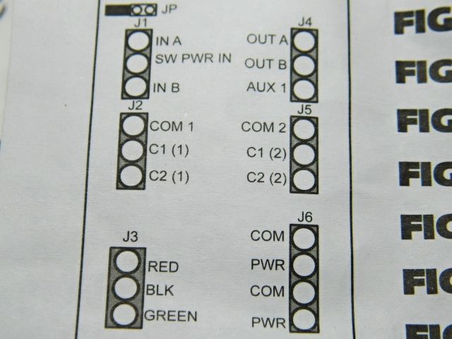
This wiring code is part of the 6924 relay board instruction packet.

Relay #18 :

Left side (6) terminals. Top down.

(J1 terminals)

(1.) In A Green (through) common input Note: Gray twist nut combines Track rail/ASC.

(2.) SW PWR IN Black  switch motor power input  Supplied from power system near the relay boards.

(3.) In B Red  (out) common input.   Note: Gray twist nut combines Track rail/ASC inputs.

(J2 terminals)

(4.)  COM 1 White is track power input from switch location for power routing.

(5.) C1 (1) Red is power routing (through)

(6.) C2 (1) Green is power routing (out) .

(J3 terminals)  Can be used to connect 6931 dwarf lights.

Right side (6) terminals. Top down.

(J4 terminals)

(7.) OUT A Green (through) switch motor power.  Relay board to switch motor terminal.

(8.) Out B Red (out)  Switch motor power.  Relay board to switch motor terminal.  

(x) Switch motor common is not supplied from this board.

(J5 terminals)

(9.) COM 2 Yellow is track power input from switch location (2nd track circuit for a switch pair cross over.

(10.)  C1 (2) Brown is power routing (through, 2nd track circuit).

(11.)  C2 (2) Blue is power routing (out, 2nd track circuit. )

(J6 terminals)

(12.)  COM/POWER   COM/POWER  are used to daisy chain constant power to all 6924 relay boards.  I think  6 to 20 volts AC or DC without look at the instructions.

Last edited by Mike CT

Just a quick update for now.  I have code running supporting outputs for 32 switches, as well as LED outputs for signals or panel lights to match.  The code also supports inputs from insulated rails for the anti-derail as well as from push buttons to throw the switches.  I do not yet have the inputs and outputs connected, but that should be the easy part.  Unfortunately, my work schedule will be limiting how much time I have to work on this, and I may take a break anyway to work on another project.  

As for physical parts, the main components needed are an Arduino board (I'm using an UNO right now), 16 channel relay boards to operate the switch machines.  In addition, I'm using 74HC165 shift registers for inputs to the arduino, and 74HC595 shift registers for the outputs.  These IC's allow just 4 pins on the Arduino control dozens of switches.

For what it's worth, my math says we have about $112 invested to build a controller for 32 switches, which includes $44 for the relay boards, $5 for the arduino, $18 for the shift register chips, and $45 for miscellaneous parts like wire, prototyping board, resistors and transistors, and terminal strips.   The cost isn't exactly free, but is pretty good considering $20 per switch to use the name brand product.  This also does not include the cost of wire to run between the controller and switches, nor the cost of push buttons to control the switches.  Most of the prices are for parts shipped from China, but are the exact same parts you would pay 2-3 times as much for from a US seller.

I'll try to get a sample diagram up of what the wiring looks like soon.  there are a lot of connections, but it is mostly the same thing over and over again.  

At this point I think it will be best to start a new thread on this switch machine controller to discuss the build.  I'll probably do that over the next couple days.  

JGL


JGL,

I certainly understand the work schedules getting in the way. I am retired and the last couple of days I had a bunch of stuff get in the way too. Hopefully will be back to normal by tomorrow. Anyway it looks like you are making good progress in spite of work schedules. I also think a new build thread would be a great idea. I will be watching for it.

Just checking in since there is some activity in the thread.  

Work has been taking up much of my time lately and I have only had a couple evenings to work on this project.  I'm currently hunting down a glitch in my Arduino code that is giving me a pretty big headache, but I'm sure I'll figure it out eventually.  Glitch aside, most of the code is working, allowing for anti-derail functionality, auto-shut-off of the coils after any programable amount of time, and outputs for control-panel and dwarf signal indicators.  

From what I have been able to understand, the Atlas signal control board is capable of detecting the physical position of the switch.  This I something I have a couple ideas on how to accomplish, but for the moment I'm thinking it is not necessary, instead relying on the operator to use electric controls to throw the switches for signals to respond properly.  If proper signaling is needed from manual throws of the switch machine, I can work on that, but all of the ideas I have add significantly to the complexity and moderately to the cost involved.  

JGL

JGL,

Don't worry about detecting manual throws of switches.

I bought an Arduino and have been working on a program so I will understand what you are doing. I actually have a program working that seems to do everything I need. The program will shut off power to the switches after a set amount of time and then keep power off for a short period of time to avoid chatter. It will also maintain power to the led indicators until the switch is changed to the other position.

Right now I am using push buttons on a breadboard as inputs to my shift registers. The register pins are pulled HIGH with 10k resistors when the button is not pressed. The button is connected to ground, so the pins become LOW when the button is pressed. Is it okay to duplicate this setup when I connect it to my layout. Can I connect the insulated rail directly to the input pin of the shift register?

I envision using one "parallel in" shift register to control 4 switches (each switch will use one pin for each direction). I will need twice as many registers for the outputs. Each direction of each switch will have an output for the led indicator and another to throw the switch. Were you thinking along the same lines?

The program assumes that each switch is connected to 2 consecutive pins on the shift register.  (E.g. switch 1 to pins A and B, switch 2 to C and D, etc.)

Here is a link to the code I have written:

Arduino program to control Atlas switches

https://create.arduino.cc/edit...cd84e2e6611f/preview


JGL,

I went ahead and started a new thread about this project.  New Thread 

I also took a stab at the wiring between the insulated rail and the shift register. Let me know if I am on the right track or if you were thinking of something completely different. 

I bought a relay module and have been testing my switches. The 1 second power application seems to work well.

RTR12,

I was a little hesitant when you first suggested using an Arduino, but I've actually enjoyed learning about it. You were right that there are lots of sample programs available which make it easier to learn the basics.

Thanks! Looks like you picked it up quickly and are doing quite well with it so far. They are pretty fascinating little devices that a lot can be done with. I suppose your imagination is the limit. The Uno is the only one I have fiddled with, but I did buy a Mega on sale a few months ago at Micro Center. It was so cheap I couldn't pass it up. Glad you are enjoying them. 

Add Reply

Post
×
×
×
×
Link copied to your clipboard.
×
×