Gang,

Originally, I planned to use some 20 gauge wire to make electrical busses for accessories and lights around the layout. But I have some barely used 14 gauge rolls of wire (white and blue) hanging around. Any foreseeable issues or problems with using these for busses? I will use suitcase connectors to run feeders to the accessory or building.

Thanks,

George
Original Post

Replies sorted oldest to newest

Hi George
The bus wire will depend a lot on the amps you plan to send thru it. 20AWG is a bit lite for most transformer outputs. The 14AWG sounds right. I use Romex around the layout thru terminal strips. And I do use the bare wire out of the terminal strip for connecting as well as the black and white. That allows me to connect a lot of lites and track power for my common grounds.

Ralph
If your layout wire runs are very long, in my opinion #14 is about the minimum Bus size to avoid voltage drop. Also, as already noted above, the load is a key issue. How many locomotives, how old--post war or modern, how many lighted passenger cars with incandescent bulbs, lighted accessories, powered track switches????

If using #20 for railpower wire drops from track-to-bus, you should consider frequent drops since #20 is pretty light for railpower load and you might well increase load in the future[#18-#16 is better].If for lighting or accessories only, #20 should be okay for drops to individual units. If you have enough #14 it can be used for both the Hot and Common Bus wire runs. Bare copper for the Common Bus is fine if you want to buy some but #12 or #14 is good.

[folks use the term "ground" for the Common Return conductor and it has become common usage--but there is no ground on a three rail o-gauge layout unless it is a "ground plane" installed for TMCC operating purposes. On a TMCC Command system the #5 pin in the Command Base serial port connector is an earth ground and can be used for connecting a ground plane but not any way ever connected to railpower--never].

You need to run a Hot[center rail feed] Bus wire for each power district or separate block or loop[each separate throttle for example].However the single "Layout Common" Bus wire is all that is necessary for any number of power districts. If your #14 is all one color you need to tag it or if white, color code it with a Sharpie near the ends to ID whether it is Hot or Common and ID which power district each Hot serves.

Some swear by suitcase connectors and some swear at them. If they make a good circuit okay, but my experience, expect more voltage drop over time.

Good luck! Smile
Last edited by Dewey Trogdon
Wire nuts are OK for some applications, but not for tapping into a continuous bus.

Is your 14 ga wire solid or stranded? The suitcase connectors will probably work better with stranded wire. Also, it is important to have the correct size connectors so that you aren't cutting wire strands with too small a connector.
Hi again George

I thought I'd explain a little more about how I connected my lites and accessores using a common bus. I run the bus wire - romex with 3 wires, black/white/bare - thru a buss bar. I purchased the 4 hole one and have them spaced around the layout. I connect the romex into three of the holes on each bus bar around the layout. I use the 4th hole to run a wire to a Euro terminal strip close to where the accessory or lites might be located. No Crimping - No Saddles. I fitted the inbound side of the Euro strip with jumpers so that each port gets the common. I connect the common lite to the other side of the Euro strip. Again no crip/saddle.

I have a lot of lites of varying types and manufacturers totaling over 225 in all so I needed some way to simplify the wiring.
HIGHWAY LITES 6-12804 LIONEL
HIGHWAY LITES MP-6081 MODEL POWER
TALL LITES 433-1705SCENE MASTER
YARD LITES - DOUBLE 6-12927 LIONEL
YARD LITES - METAL RK-1060 MTH
YARD LITES - METAL 6-14071 LIONEL
STADIUM LITES 56-52845 DEPT 56
PORTABLE SPOTLIGHT 6-22354 LIONEL/K-LINE
PORTABLE SPOTLIGHT K2350 K-LINE
PORTABLE SPOTLIGHT PA-008 T & C
PORTABLE SPOTLIGHT MP-6101 MODEL POWER

The common theme is the wires are like strands of hair. In some cased I needed to pig-tail stronger wire onto them using 20 AWG with the grey wire nuts and connect these pig-tails into the Euro strip. If you follow the description in one of the previous posts about folding over and doubling up it will work easily and I have had no failures so far. I do the same technique to get the power side to the toggle/Relay I described to you in an earlier post.

Hope some of this helps
Is there a "Sparktrician" in the house? Big Grin or, perhaps a Eek "Bus-trician"!
Long ago on here a debate over the spelling of "Bus" broke out and lasted quite awhile.
I made the mistake of noting that my 1940s Navy training manuals used the term "Buss" and a couple of EEs agressively took me to task, one guy noting that a buss was simply an old fashion term for a kiss!
Agreeing that both me and the Navy manuals were likely old fashion, and perhaps obsolete[although we kept the lights on and guns firing]. Nevertheless I noted that I was going to install a Buss on my old fashioned and obsolete layout. However they were not forgiving of my "grevious error" as it was described.

Point: lot of both old and modern ways to "skin a cat" so whatever you do just make good solid connections and color code or mark your conductors so you can trouble shoot Cool.
Some very good information here. A couple of points to note IMO.

Dave's comments on the suitcase connectors are from a mechanic who has repaired/replaced/fixed a problem, most likely more than once. He even commented that they work much better with solid wire. Wink I can add that I've repaired/replaced/fixed this problem more than once. These current connectors are a potential problem IMO, I've repair a few of these, but they may work well for you on your layout.

There are a lot of connections/termination on a modern model railroad, easily into the hundreds even on a smaller layout. If you can make a connection that is reliable easily, and quickly then have at it. Again IMO.
quote:
Originally posted by Mike CT:
Some very good information here. A couple of points to note IMO.

Dave's comments on the suitcase connectors are from a mechanic who has repaired/replaced/fixed a problem, most likely more than once. He even commented that they work much better with solid wire. Wink I can add that I've repaired/replaced/fixed this problem more than once. These current connectors are a potential problem IMO, I've repair a few of these, but they may work well for you on your layout.

There are a lot of connections/termination on a modern model railroad, easily into the hundreds even on a smaller layout. If you can make a connection that is reliable easily, and quickly then have at it. Again IMO.


Mike,

I'm not using the connectors you referenced. Mine are these - the 1st one shown. See any problems with these?

Thanks,

George

John any heavy duty plug is fine.
If you looking for a easy cost effective way Dewey a while back hit on the multi pin trailer plugs . They come in 4, 6 , and 8 pin variety's and are directional so she can't plug them in but one way. If you really want cheap you could buy the simple 4 pin flat trailer plug. I think the male/ female combo's are about 5 bucks at the auto parts store.
So she can keep em straight you can just paint the plugs with different color paint or use colored tape.

Coarse you know you want to keep the 120 volt stuff to a minimum under the layout.
If you do wire her some outlet's make sure you wire it to code with all your connections inside an inclosure(Box) no wire nuts just floating in thin air.
I'll check back on this thread. Let me see the pic's when you get a chance and we'll figure something out.

David

Originally Posted by DPC:
Funny,

A Buss is for carrying electrical current

A Bus is what your kids ride to school Big Grin

David


I beg to differ, Dave.


A bus is what carries your kids to school; OR a (relatively) large-diameter wire or metal strip that carries electrical current safely, if sized properly.


A buss is a kiss. Happy Valentine's Day!


Buss (initial letter always capitalized) is the name of a company that makes fuses.


It's nice to see that many of the participants in this thread seem to have it right. It wasn't always so....


wolverine 

DPC-


Making progress.  Do you know of a good site for information on relays?  I came across the idea in the thread on control panels and liked the idea of having smaller current on the control panel flip the relays to control the actual power.  I understand what a relay is but I am having a bit of trouble figuring out how to translate the descriptions at the electronic storesfronts.


For example, for my track I have the MTH big transformer, so I have two seperate controllers - I would like to set all my blocks to be able to run from either handle (controller) - so I am pretty sure I want a SPDT type of relay - but I would like it normally off, but could be energized in either of two positions.  Along the same way I would like to use one for my switches as well.


Anyone have any ideas?  I have studied the circuit diagram someone else posted and understand it, just having trouble figuring out exactly what relay to buy.


-John


Originally Posted by Johnedko:

DPC-


Making progress.  Do you know of a good site for information on relays?  I came across the idea in the thread on control panels and liked the idea of having smaller current on the control panel flip the relays to control the actual power.  I understand what a relay is but I am having a bit of trouble figuring out how to translate the descriptions at the electronic storesfronts.


For example, for my track I have the MTH big transformer, so I have two seperate controllers - I would like to set all my blocks to be able to run from either handle (controller) - so I am pretty sure I want a SPDT type of relay - but I would like it normally off, but could be energized in either of two positions.  Along the same way I would like to use one for my switches as well.


Anyone have any ideas?  I have studied the circuit diagram someone else posted and understand it, just having trouble figuring out exactly what relay to buy.


-John


Ebay can be a good source. If you get stuck I sell them at my cost. I have a good supply  of them.


Dale H

I don't really see the need for the relays?
Single pole switch or single pole double throw with center off should be all you need.
The relay would just be adding a second electrical apparatus into the mix to complicate things.
If you had a huge amount of current draw yes then use the relays but for normal operation on most layouts it's overkill.

Sidings and yard tracks should be on switched power.
You can double up a channel on the Z-4000 by using 2 single pole switches(Heavy duty) That way you can have track 1 ON and track 2 OFF or the reverse or you can have them both ON
This will be a much simpler set up and less expensive than trying to use relays not to mention the spider web you'd have.

David

If you have a larger layout lets say your bus size is 16 gauge . Lets say you have a number of sidings and blocks to switch on and off with toggle switches,mounted in a central control panel. From each siding all these 16 gauge wires have have to be run to and from the control panel. A lot of extra expensive wire, a lot of potential voltage drop since the run is longer and the wires are run in a zig zag path. With DCS I guess this would be paired twisted wire which would include the common also. Not sure since I run conventional.


Now instead we use a bunch of relays mounted in line right in the path where the wire runs directly to the siding.. DPDT 15 amp with sockets cost about $8 each. Think of them as screw terminal barrier strips with a remote switch in the middle (the relay coil) which can make or break or make/break one,2 or 20 circuits in tandem according to needs. All that is needed then from the control panel is 1, 22 gauge wire from each light duty toggle switch run to each relay coil or it can be switched with 2 push buttons,described in the link below. A separate power source is needed for the relay coils 10 volt or 18 volts depending on relays used. each relay coil uses maybe 1/3 watt of power.


http://www.jcstudiosinc.com/BlogShowThread?id=635&categoryId=426


A good example of this application is your automobile. The wire from your battery to your starter motor is I think 8 gauge or something. When you turn the ignition key a small gauge wire from the switch activates a relay coil (solenoid) mounted somewhere in line from the battery cable to the starter. The relay coil then closes contacts which switch a larger amount of current to run the starter motor until the car starts. If this method was not used a thick 8 gauge wire would have to be run to the dash  from the battery and connected to a very heavy duty switch,which would take some effort to turn,then run to the starter. Not using the relay would actually cost more since heavy copper wire is expensive as is a heavy duty multi contact switch and the system would not be very user friendly.


Yes, you do not "need" relays,especially if you have a 4X8 layout on saw horses. But if you have a larger complicated layout, the  use of relays allows for easier simplified organized wiring and actually saves money if you consider savings in wire and switches. In industrial settings,the use of relays is standard practice and common place. 


In addition relays can be coupled with timers, and relays can do very complicated switching functions such as excluding 2 circuits from being on at once. Throwing a single switch for example can stage a sequence of events if desired.


Dale H


I think you're missing the point - not only do you have to factor in the cost of heavy-gauge wire and high-ampacity switches, but with relays you could run just one little wire from each block relay to your control panel.  Use a DC supply for your relays and they're dirt-cheap.


The command signals are also probably happier not winding their way through a forest of cables out to the control panel and back again.

I just explained that it avoids a rats nest of heavy wires in and out of the control panel to the operating switches. You dont seem to see that or want to see that.. That is a big advantage. Suppose you want to throw 6, 10 amp circuits with one switch. Are you going to use a 6pDT toggle? Gonna connect 2, 3PDT with a bar? Suppose you want a safety lock out where 5 circuits must be off while 5 others are on. Lets say you want sidings A,B and C off while sidings D E and F are on and there is no way both can be on at once due to operator error.  How do you do that with toggle switches? What if you want to turn a circuit on and off with 2 push buttons instead of a toggle? Suppose you want to sequence 2 or more events accurately  after a switch is thrown? Suppose you want delay off? Easy with multi contact relays. Not just about switch heavy loads.  What about the circuit in your car that turns your lights out 2 minutes after you get out of it so your can get your keys,get in your house and not have your battery go dead? You think Ford does that with Toggle switches?


And what about my garage door opener or my alarm system. Maybe a manual switch could be turned on mechanically if someone breaks the door in, then we do not need those expensive $8 relays in the circuit.


I do not advocate using relays just for the sake of using them. I said in large layouts with complex switching they have advantages.


If you want KISS go back to a hand crank on your car,then you dont need the battery or starter or relay.  A bit inconvenient though. And for your block signals use one of those old 153 contacts,you dont need a relay for that. Or just use a toggle and switch it yourself when the train goes by.


Dale H


Originally Posted by Dale H:

I just explained that it avoids a rats nest of heavy wires in and out of the control panel to the operating switches. You dont seem to see that or want to see that.. That is a big advantage. Suppose you want to throw 6, 10 amp circuits with one switch. Are you going to use a 6pDT toggle? Gonna connect 2, 3PDT with a bar? Suppose you want a safety lock out where 5 circuits must be off while 5 others are on. Lets say you want sidings A,B and C off while sidings D E and F are on and there is no way both can be on at once due to operator error.  How do you do that with toggle switches? What if you want to turn a circuit on and off with 2 push buttons instead of a toggle? Suppose you want to sequence 2 or more events accurately  after a switch is thrown? Suppose you want delay off? Easy with multi contact relays. Not just about switch heavy loads.  What about the circuit in your car that turns your lights out 2 minutes after you get out of it so your can get your keys,get in your house and not have your battery go dead? You think Ford does that with Toggle switches?


And what about my garage door opener or my alarm system. Maybe a manual switch could be turned on mechanically if someone breaks the door in, then we do not need those expensive $8 relays in the circuit.


I do not advocate using relays just for the sake of using them. I said in large layouts with complex switching they have advantages.


If you want KISS go back to a hand crank on your car,then you dont need the battery or starter or relay.  A bit inconvenient though. And for your block signals use one of those old 153 contacts,you dont need a relay for that. Or just use a toggle and switch it yourself when the train goes by.


Dale H


Well I don't use the OLD 153 block signals and I don't see any need to switch 6- 10 Amp circuits all at once and if you park your car on a hill you don't have to hand crank it so there!
This electrical forum is full of people trying to show every one the most complicated way of doing anything there is . I don't know if it's a need to impress everyone with their knowledge or to hear themselves think but it does confuse the heck out of anyone trying to wire their layout for the first time  when simple explanations would do just fine and Dale your always  one of the ones with 15 paragraphs explaining the best way to screw in a light bulb.
You all can have this forum it's over populated with know it alls and I'm more then done with it.
To the original poster - My email is in my profile if you want help,I'll be more than glad to help you any way I can but I won't be posting here anymore.
David

Originally Posted by DPC:
Originally Posted by Dale H:

I just explained that it avoids a rats nest of heavy wires in and out of the control panel to the operating switches. You dont seem to see that or want to see that.. That is a big advantage. Suppose you want to throw 6, 10 amp circuits with one switch. Are you going to use a 6pDT toggle? Gonna connect 2, 3PDT with a bar? Suppose you want a safety lock out where 5 circuits must be off while 5 others are on. Lets say you want sidings A,B and C off while sidings D E and F are on and there is no way both can be on at once due to operator error.  How do you do that with toggle switches? What if you want to turn a circuit on and off with 2 push buttons instead of a toggle? Suppose you want to sequence 2 or more events accurately  after a switch is thrown? Suppose you want delay off? Easy with multi contact relays. Not just about switch heavy loads.  What about the circuit in your car that turns your lights out 2 minutes after you get out of it so your can get your keys,get in your house and not have your battery go dead? You think Ford does that with Toggle switches?


And what about my garage door opener or my alarm system. Maybe a manual switch could be turned on mechanically if someone breaks the door in, then we do not need those expensive $8 relays in the circuit.


I do not advocate using relays just for the sake of using them. I said in large layouts with complex switching they have advantages.


If you want KISS go back to a hand crank on your car,then you dont need the battery or starter or relay.  A bit inconvenient though. And for your block signals use one of those old 153 contacts,you dont need a relay for that. Or just use a toggle and switch it yourself when the train goes by.


Dale H


Well I don't use the OLD 153 block signals and I don't see any need to switch 6- 10 Amp circuits all at once and if you park your car on a hill you don't have to hand crank it so there!
This electrical forum is full of people trying to show every one the most complicated way of doing anything there is . I don't know if it's a need to impress everyone with their knowledge or to hear themselves think but it does confuse the heck out of anyone trying to wire their layout for the first time  when simple explanations would do just fine and Dale your always  one of the ones with 15 paragraphs explaining the best way to screw in a light bulb.
You all can have this forum it's over populated with know it alls and I'm more than done with it.
To the original poster - My email is in my profile if you want help,I'll be more than glad to help you any way I can but I won't be posting here anymore.
David

Sorry I come across that way. My sincere apologies to you and everyone on the Forum here. My layout has 12, 10 amp circuits just for the lighting so I thought everybody else did too. In the future I will combine all 15 paragraphs into 1 ,then my posts will not seem as long. The light bulb screws in counter clockwise about 3 turns as I remember or was it clockwise,ya that's it clockwise. Being ambidextrous this was always hard for me to remember. I just hold the bulb and have 3 people turn the ladder. Believe it or not the first time I did this the guys turned the ladder in the wrong direction and the bulb would not go in. Then I knew something was amiss. After a long conference we decided to try up and down before we even thought of turning the ladder clockwise.  Unless it is a bayonet base,then it just twists about 1/4 turn,I can do this myself without extra help.  I have a special tool for those hard to get miniature bulbs,it has a rubber end that fits over the bulb end. Never press too hard when unscrewing and do not oil the insert,it makes the bulb slip in the rubber... Then again some bulbs just push in and have 2 pins like halogens,if you try to unscrew them ,you can break the pins. Now for fluorescent     ( tube variety not the compact ones also filled with Mercury). They have 2 pins on each side,in that case you push and twist 1/4 turn. Now the tubes with the single pin,push into one side of the fixture ,then hook into the other side and let it spring shut. Now some train light bulbs are hard wired in. Be a mistake to try to unscrew in either direction. Hope this covers screwing in light bulbs for everyone and is not too tedious of an explanation. Since this is a family forum I can not discuss other forms of screwing other than screws which attach things. I know constant blather can be irritating so I will end this post here. There is much more I could write about,such as bulb shapes sizes  amperage,wattage and voltage as well as light spectrum and lumens that each one emits frosted and clear.. Sorry I neglected neons,maybe in my next post.


Dale H

Last edited by Dale H

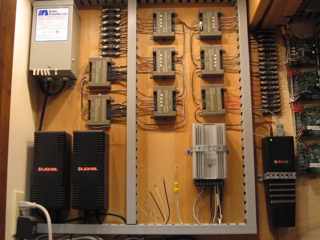
Surprisingly the Lionel BPC (Block Power Controller) is designed to handle two power sources with four outputs as was the original IC controls BPC.  I had my layout hooked up that way for awhile. You are able to toggle between Power Source #1, Power Source #2 and OFF using the handheld Cab 1.

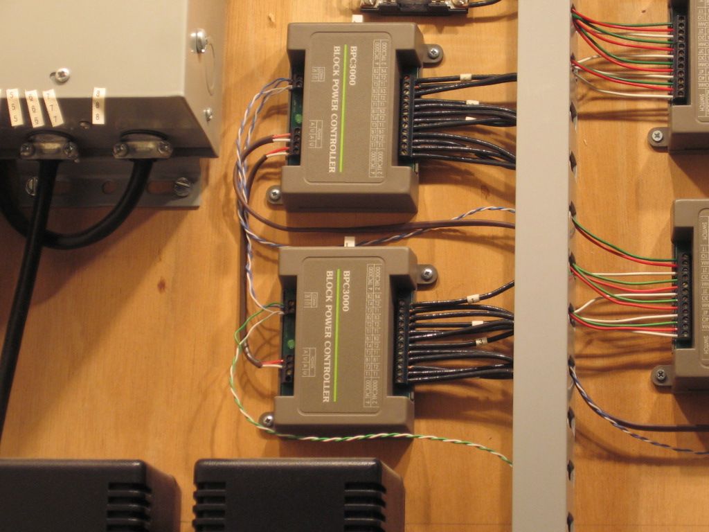
These IC Control Block Power Controllers are still wired for two sources. There are (2) Inputs and (4) outputs as wired. All is controlled with a Cab1. These have 15 amp rated contacts, Lionel has up the contact rating to 20 amps an important feature of a relay used to control track power, mostly due to dead shorts caused by derails. To take it one step further the (8) fused blocks pictured above the (2) BPC limit every output of the BPC's to 7.5 Amps.  Discussion of MTH AIU control usually lead to the AIU contact/circuit ratings to be considerable less than track demands requiring the installation of Track control relays that would compensate for dead short derail insanity. The track control relays would be controlled by the AIU outputs.


Note the space where there is a missing TPC400 (Track Power Controller), to the left of the silver box, lower right, The second power source.  Idea was to have one TPC set to conventional and one to command, then a section of the layout could be operating conventional at the same time as another section was being operated in command mode.  It did work, but with limited conventional use of (3) MTH PS2 locomotives, it was much easier to just shelve these steamers and run straight command TMCC.  


Note track power wiring to the right of the controllers, (12 wires) 14 solid the max each terminal would accept. There are (8) power input wires per controller, requiring two splices, (5) wires each, one input for each TPC output spliced to (4)wires, one for each required input shown on the BPC, all hidden in the cable tray.  And (4) outputs to (4) track blocks via the fuse blocks shown. The (2) controllers handle (8) power districts.   Red/White to the left is controller/relay power and the twisted pair (blue/Bluewhite or green/Green white) is TMCC signal.


Last edited by Mike CT

Dave,


Please don't wander off - I can't speak for the others but I highly value YOUR input (which is why I asked for your input specifically).  I would be sad if my question sparked the thread that lead to you wandering off.


My interest in the relays is for a couple of reasons:


1) I realized then when I was playing with some HO stuff as a teenager for automated signals I was actually using a pair of relays - so I have actually used them before.


2)I like to learn new things, especially with electronics.


3)While my current layout is only 6' by 8', ultimately I will have the entire room filled with an around the wall layout of 24'x12' (and there is a second room of 28'x40' that is available for future use).  So I am trying to learn a technique here that while overkill for the current layout will teach me what I need to know for a future layout.


4) I want to have an illuminated panel with different colored LEDs showing which path is electrified (did I mention I have three young daughters who I will be training on this?) as well as having indicator lights for the switch directions.  The relays seemed to offer me that option without have too much of a rats nest underneath.  (Ie keeping the 14 gauge stuff elsewhere and just having light stuff on the panel.)


-John


Originally Posted by Johnedko:

Dave,


Please don't wander off - I can't speak for the others but I highly value YOUR input (which is why I asked for your input specifically).  I would be sad if my question sparked the thread that lead to you wandering off.


-John


I second that. Dave is a nice guy,if I offended him I am sincerely sorry. Just having a bit of fun here,no offense intended. 


Dale H

gunrunnerjohn-


I am pretty sure that there are relays that will go to multiple positions (just like you can have toggles with multiple positions).  (The one I was looking at was specifically a DPDT version).


DaleH,


I don't use ebay (don't have the time) - but I am looking for someone to help me with the technical details of a relay with this.  I don't need a source to buy them, just some information so I can make a reasoned decision on buying them or not.


http://www.jameco.com/webapp/w...001_10001_2095390_-1


For example, with the relay above, it notes that the Coil Voltage is 4.5VDC and the Contact Voltage is 250VAC/220VDC.  I am assuing the "coil" means what is needed to throw the switch, while the "contact" would be how much current the switch could handle (in this case at 5 amps not enough to run trains on).


Also, it is called a DPDT - but it appears, to me, that when unergized it goes to one circuit and when energized it goes to another, so it is a "ON-ON" relay, while I am looking for a "ON-OFF-ON" relay.  Is that true?  I am just guessing here.


What key words should I look for in the documentation that can help?  THat is the kind of information I am looking for.


Thanks!


John


If you're looking for an on-off-on relay, that sounds like a pretty specialized beast, do you have an example.  In any case, I can assure you that an oddball configuration will be expensive, so I'm also sure there are lots of cheaper alternatives if it does exist.  I've personally never heard of such a relay, and I've been doing this for a long time.  I'd be glad to be proven wrong, education is never a bad thing, but I think you're on a snipe hunt. 


A DPDT relay is just that, two poles that have a NC and a NO contact.  It only has two states. 


gunrunnerjohn-


Okay, I think I understand your earlier post better now.  The "energized" was the key bit I didn't really understand until I read your most recent post.  The DPDTs I am seeing would mostly be "ON-ON" switches, the problem is the "OFF" portion.  For that you would need something with a second coil, or something like that?


Thanks!


-John


OOPS!  With two relays, you can have multiple choices.  Do you want to interlock them so that only one relay can drive the output at a time?  Probably, in your case. 


You don't wire the normally closed contacts together, but rather the swinger/armature for the power path.  You can use a second set of contacts so that the relay coil of one is energized through the normally closed contact of the other relay.  That way, if one relay is energized, the other relay is locked out - first come, first served.

Post
×
×
×
×
Link copied to your clipboard.
×
×