What works best for wiring the turnout motors on ROSS switches, 26ga twisted pair or 28ga twisted pair? Most runs will be 20' approx for this batch.
Replies sorted oldest to newest
I have used cat 5 and by twisting two conductors together making one conductor. works well for me .wire gauge is the sum of the conductors.
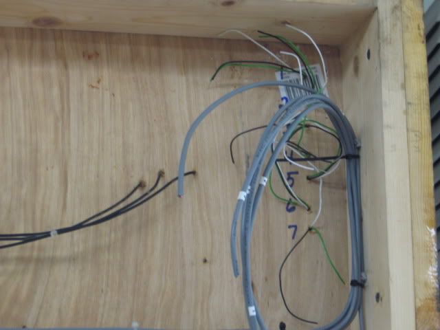
Pictured is 22 gauge 4 conductor cable. Most of the time (3) conductor would work, on occasion, you would need the 4th conductor). (4) conductor was available that day. 7/14 switches, (2 locations), wired to (4 cross-over pairs) and (3) individual switch motors, (7) marked on the underside of the layout.
Lionel SC-2 input (TMCC control of (6) throws), (4 cross over pairs, and two individual switches). One switch was push the button(s) only.
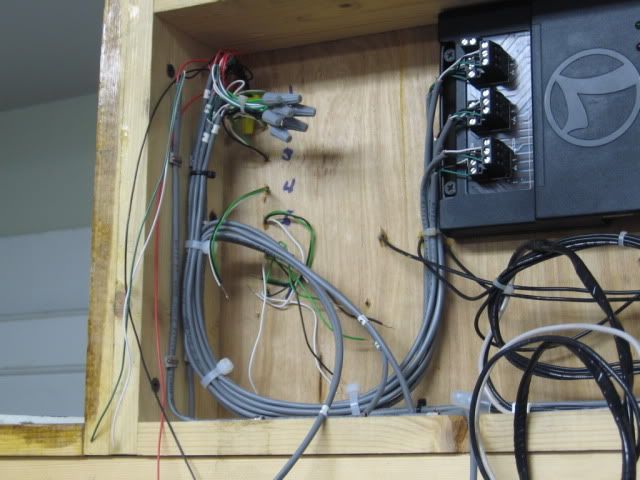
Switch motor connections. The black wire was not used. There are (2) switch motors for the (number one cross over) and there would also be non-derail inputs in this splice.
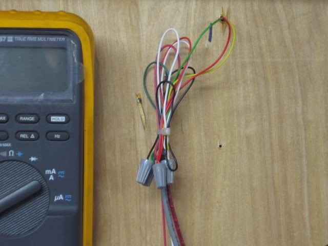
One set of (7) DZ 1002 switches wired.
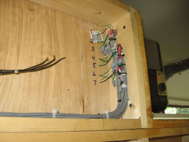
The other seven DZ 1002 switches and the SC-2 wired complete.
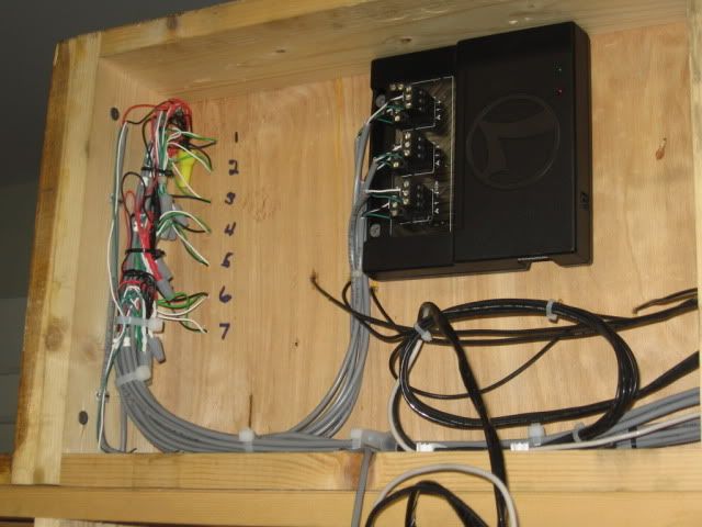
There were also DZ 1008 relays used for power routing, which required the 4th wire as a common. Relays for switch pair #4 and switch pair #5. 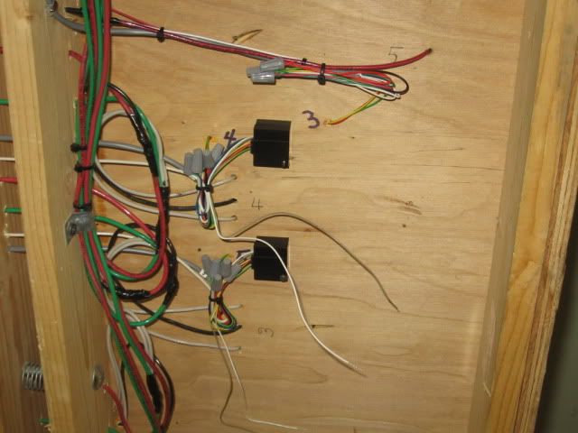
Top side view.
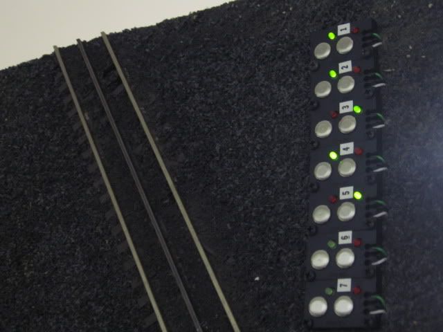
There are two control points one on either side of the "Y" module, in addition to the SC-2 pictured, for TMCC control.
Here is switch testing with a Rich Yoder GE 44 tonner. Mouse over the image and click on the triangle for a video.
Small wire nuts are Ideal (Grey 71B, 30-071. Minimum of (2) # 22's, Maximum of (2) # 16. Also, 3M Highland H-29 wire nuts. Splicing small wires like this may require pre-twisting and folding the wires over to get a good tight connection with the wire nuts pictured.
Wiring was done with the "Y" module vertical.

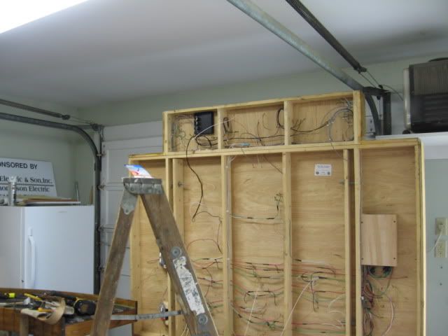
Nice wiring - clean. Mine is a rats nest in comparison.


