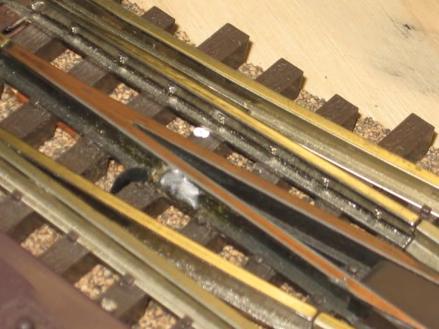
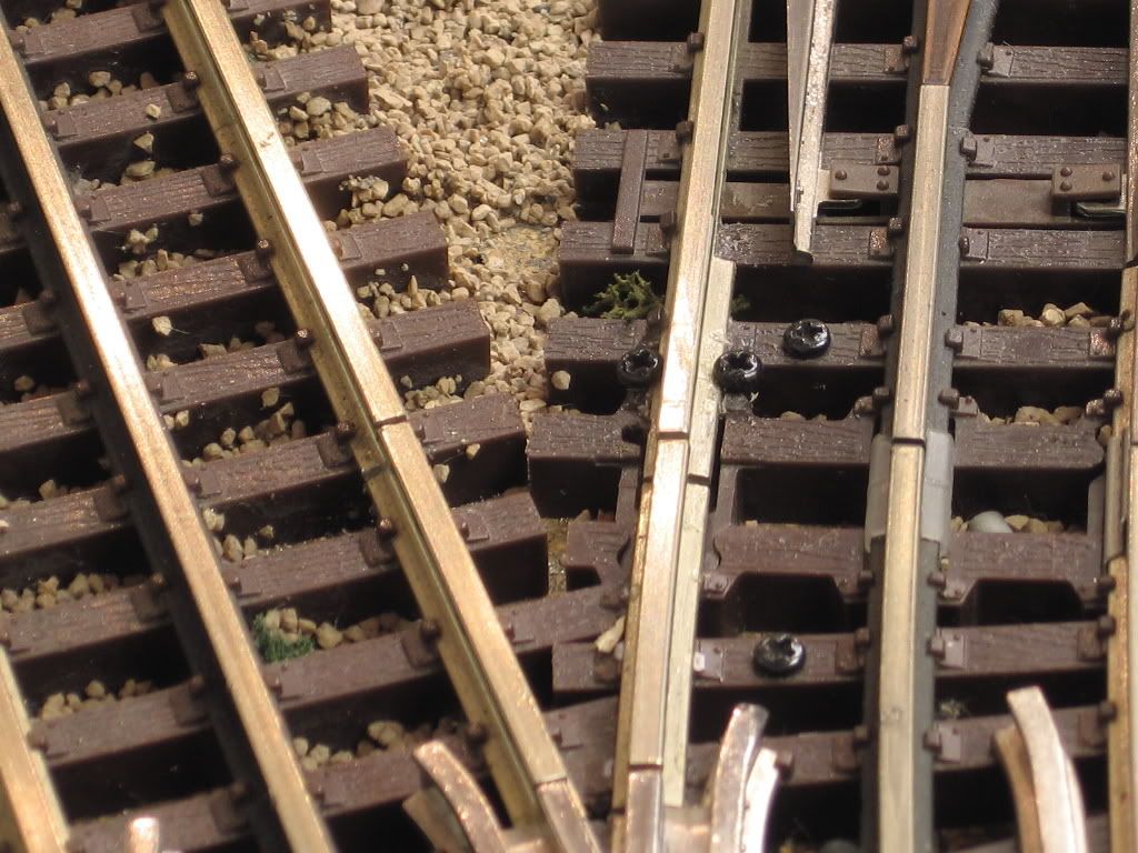
I have just had an Atlas O 054 left-hand switch fail. It's not the electro magnet (switch machine) but the underside embedded wiring that transfers power on down the track. They seem to fatigue over time and break. The worst part it is in a blocked switching yard area meaning a lot of track has to be lifted. Has anyone had much luck powering the dead track with another set of power shoes and leaving the broken Atlas O switch in place? OR do I just bite the bullet and find another Atlas O 054 left-hand and replace it?  Finally, have any of you experienced the same problem of broken wires underneath the switch in the area of the frogs?


Original Post

Replies sorted oldest to newest

Yes, we have had several of those wires underneath the Atlas O switches fail on our club layout.  We installed most of these switches circa 2002 when Atlas was using thin wires (they use thicker wires or bus bars on their switches now).  Our normal solution is to solder a short wire from the center rail on the connecting track to the switch rail.  However, the center rail on the switch is made of some alien metal that will not hold solder.  So what I have had to do was to drill a small hole through the bottom of the center rail on the switch and feed a copper wire through it.  Then I fill the hole with solder the best I can to secure it and solder the other end of the wire to the connecting track.


Thanks Roger. Are you part of the group that runs the trains at Balboa Park? If so, I'm the guy that donated the track cleaning cars to the exhibit. I checked the Atlas On Line Store and they have a switch in stock, probably close to $125.00 with shipping. That's a killer. I'll try to repair the switch. Does the break occur between the center track and the frog? And I know, I've tried soldering the tracks before without any luck. 

Yes I am part of the Balboa Park group, and thanks for the track cleaning cars.

The alien metal part is the black center rail as shown by the arrows:

Atllas-1

The problem is the jumper wires on the underside of the switch which will sometimes burn out:

Atllas-2

The ideal solution (if you can remove the switch) is to unscrew the jumper cables, drill a bigger screw hole, and attach a larger gauge wire that you can connect directly to your power bus under the layout.  However, if you can't remove the switch, you can drill a small hole through the bottom flange of the center rail and feed a solid copper wire through.  Then solder the other end of the wire to the center rail of the track attached to the switch:

Atllas-3

After you solder in the jumper wire, write over the wire and solder with a black Sharpie and no one will notice.


Attachments

Images (3)
  • Atllas-1
  • Atllas-2
  • Atllas-3

I can't find anything to suggest the alien metal 3rd rail is anything but the same  nickle-silver used in the other rails.  It seems the blackening process just makes the metal not want to take solder.  Has anyone tried taking a file, sand paper, or small dremmel tool grinding wheel to the side of the rail to remove the coating?  

JGL

Atllas-1What I've done to my switches when I have this problem is to solder the connecting center rails together. You need a high powered solder gun that gets the metal very hot, very fast to make this work. Once I solder both rails together, I then sand the solder down real smooth so that the rollers on the engines can roll over the center rails smoothly...................Roger

Attachments

Images (1)
  • Atllas-1
Last edited by ROGERW

Note that the metal cast V-shaped rail section center of the switch, as mentioned does not accept solder well.

I have had success removing the blackening material carefully allowing the copper clad under the black to remain. The copper clad makes soldering a bit easier.

Note the copper on this switch, sand too much, and the copper color goes away. This part of the switch does not appear to be nickel silver, which accepts solder relatively easy, may be, made of a cast steel, with the copper coating shown.

Sorry, not one of my better pictures, but with care you can solder to the "V"-shaped piece.  Note the picture.

Idea, is to fix a switch without lifting it from a layout. IMO. 

 Mike CT


Last edited by Mike CT

We have a similar conductivity issue with "dead" AtlasO 2 rail turnout frogs.  There is a manufacturing/design weakness with AtlasO turnouts - the electrical path between the cast rail/frog pieces and the metal feeders molded into the plastic ties sometimes fail.  To prevent the problem I solder feeder wires directly to the cast frog.   It isn't easy to solder to the cast metal but with enough heat and flux it can be done.  As others have pointed it is important to shine up the metal on the casting.  I carefully use a motor tool with a cut off wheel (eye protection a must..) to grind the finish on the side of the casting.  Then apply flux and tin the casting with solder.  Pre-tin the feeder wire and then solder the wire to the casting.  If you use a high heat gun you can get in and out before the plastic ties melt.  I use a dual heat Weller 260/220W gun.

Ed Rappe

Last edited by Keystoned Ed

Forum member Ingeniero No1 (Alex) came up with a great way to power Atlas track without soldering. It is described here Hidden Pass Junction RR in his build thread (about half way down on page 2 of the thread). He even gives us the drill bit size, wire size and screws he used, he's done all the head scratching for us and was kind enough to share the information. All you will need to do is figure out how to hide the wires. One way would be to go under the table and come back up. I believe you could easily fix your problems using Alex's methods.

I stole the idea and used Alex's method to connect all power to my layout, it is very easy and works very well. It is also very easy to re-arrange things if you make changes or add on. I was glad I found Alex's build thread before making my layout more permanent.

I have some old switches I purchased used that have the small wire jumpers. As others have stated, the newer ones use larger wire. I do not have any of the newest Atlas switches yet, but they are supposed to have even more improvements than the previous ones.

Last edited by rtr12

I've soldered to the "Alien metal" of the Atlas switch, I just scrape all the blackening off it.  I always thought it was the same as the rails.  We had a bunch of older Atlas switches that the flimsy thread burned out and we had to jumper.  Since I didn't want to lift them, I just run a wire under the table between the two points.  I use a heavy enough wire so I only have to do it once.

Atlas corrected the wiring problems as well as other with the second (?) release of switches.  You can identify them because on the box it says "UV protected".  It is also cast into the underside of the plastic ties.

The "problems" with Atlas switches comes up frequently.  It is a rehash of problems from many years ago.  As long as you buy new production you will be fine.  Be wary of buying used and off ebay.  Check for UV protection.

Trainworld has O54 switches for $80.

Jan

Modelrailroader posted:

Last question, do the current run of turnouts from China correct any of these problems?

Robert, I would also like to know the answer to this question!  I picked up the handout pictured below from the Atlas folks at a train show last January.  As you can see, it highlights all of the planned changes to the design and production of the Atlas switches, most of which were supposed to address the known "issues". 

Well, the switches are finally starting to arrive here in the States...and I would love to know if any or all of these improvements were in fact made.  I'm really hoping that as the latest batch of switches start to make their way onto the layouts of some of our fellow Forum members, they will be kind enough to post their opinions, comments and reviews here!  I will be building a new layout in the near future and still haven't decided on what track I'm going to use yet.

Atlas Switch & Turn-out Improvements

Attachments

Images (1)
  • Atlas Switch & Turn-out Improvements
Jan posted:

Atlas corrected the wiring problems as well as other with the second (?) release of switches.  You can identify them because on the box it says "UV protected".  It is also cast into the underside of the plastic ties.

The "problems" with Atlas switches comes up frequently.  It is a rehash of problems from many years ago.  As long as you buy new production you will be fine.  Be wary of buying used and off ebay.  Check for UV protection.

Trainworld has O54 switches for $80.

Jan

Thanks for the tip on the UV marking on the newer boxes. I agree with you on all counts. As you say, I think a lot of folks still refer to problems with the original releases of the Atlas switches. I have not had any problems with their newer switches.

Glad to see some of you were able to solder wire to "V" rail.   Depending on the location of the failed switch on our club layout, we were most times not in a good position to try hard enough.  Also, we were always afraid of melting the plastic spikes.  Because if we botched the job, then we would have to replace the switch, which was a lot more work.  The "drill and fill" method I described above was relatively quick to do and allowed us to use a lower power soldering iron.

I really like Atlas O switches even despite the problems mentioned.  The good people at Atlas O donated a lot of track and switches to our club when we were building our layout during 2000-2002.  If we need to replace a switch, and still have one of the old models, I just simply re-drill the jumper wire holes on the bottom and attach larger gauge wires before we install the switch.

The photos and repair suggestions are outstanding. I ended up replacing the switch which was in a yard, a nightmare because of all the connecting switches. I am going to try to power the frog by drilling a couple of micro holes and running a jumper direct to the frog from the center rail. 

On the downside after I installed the new switch I somehow jammed a  Z1000 switch motor. The motor survive but the Z two button controlled fried. I asked Zander but haven't heard back......do you know if an Atlas O switch controller can be substituted for the Z Stuff controller? 

Thanks for all your suggestions !

Dave

gunrunnerjohn posted:

I've soldered to the "Alien metal" of the Atlas switch, I just scrape all the blackening off it.  I always thought it was the same as the rails.  We had a bunch of older Atlas switches that the flimsy thread burned out and we had to jumper.  Since I didn't want to lift them, I just run a wire under the table between the two points.  I use a heavy enough wire so I only have to do it once.

The black finish on the center rails of our Gargraves track and Ross switches is also very hard to solder. We did something similar to what gunnerjohn did. I use a small narrow abrasive bit in my Dremel. I put the rounded tip on the side of the rail (flat side area between top and bottom of rail) and then grind off a quarter inch or so of  the black finish. Then it is easy to solder. 

John

I get a kick out of reading some posts of failures. Of course they all blame certain things.

I wouldn't expect my switches to carry the current for a full large consist on my RR, while I have high amp draws. I would run my own jumpers at the least. Most of my blocks are created so the switches are at the very ends. They may carry the current of a single engine passing over. They don't have to carry the whole train's draw. I don't think it's just one manufacturer's switches. I don't think there are many switches out there that can carry ten amps or more thru these small jumpers. I believe they're just intended to carry current thru the switch to prevent stalling.

Building a large G scale RR outside helps me learn how to handle current draws. Anywhere there's a weak point shows up real fast. There are many ways to fix these issues. The best is to learn before burning up stuff or creating failures. I've had a lot of experience from the later, though.

I was just about to ask, how do you prevent the plastic ties from melting when you use so much heat from a soldering iron?

Has anyone had problems with the plastic ties melting right away?

Last question, do the current run of turnouts from China correct any of these problems?

I’ve melted the spikes on the ties with soldering. I just epoxy the tie to the bottom flange of the rail.
Alan

A few pointers from one who has had to troubleshoot issues:

  • Like Joe said, don't rely on internal turnout wiring. Put in your own feeders. I actually prefer turnouts that aren't wired so I have control over what's live and what's not, and what power source is used (great for sidings).
  • Try NOT to use too many mounting screws on turnouts as thermal shifting of benchwork can cause the turnout to go "out of plane" and cause derailments, even with hi-rail flanges.
  • Be prepared to deal with shifting rails, loose spikes, etc over time. I've had to re-spike some Ross turnouts over the past several years as some work loose from all the traffic in a club environment. When re-spiking, put a dab of carpenter's glue on the spike before driving it back in.
  • On Atlas track, if you lose a "spike", chisel off the stub, drill a small hole with a micro drill in a pin vise and drive in an O scale spike with a little dab of epoxy. That should hold the rail in place.

After re-spiking rail, I've come to appreciate (i.e. -- not fear) the thought of hand-laying track.

Add Reply

Post

OGR Publishing, Inc., 1310 Eastside Centre Ct, Ste 6, Mountain Home, AR 72653
800-980-OGRR (6477)
www.ogaugerr.com

×
×
×
×
Link copied to your clipboard.
×
×