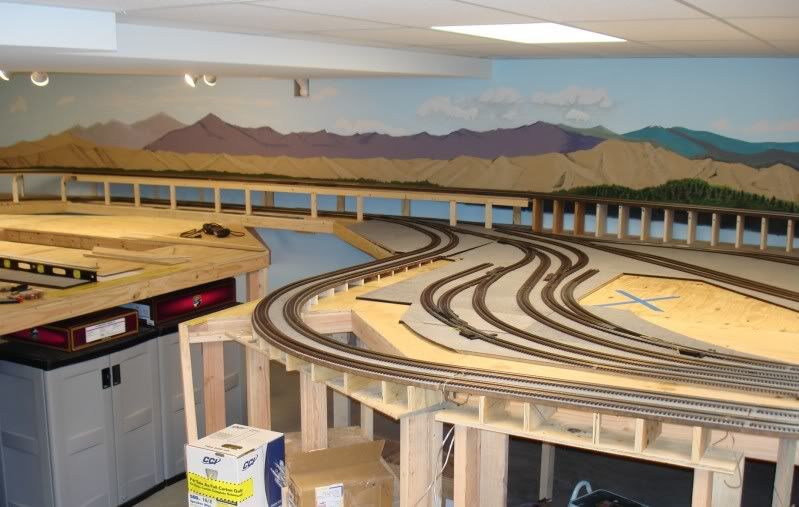
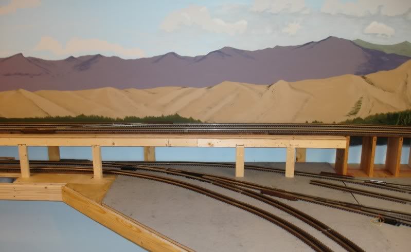
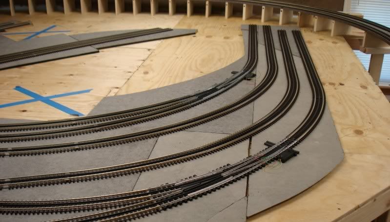
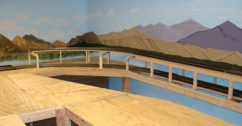
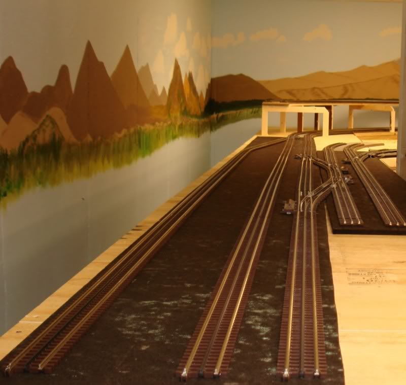
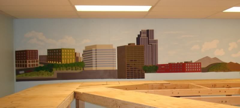
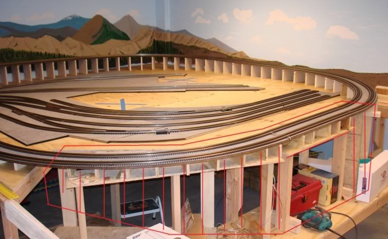
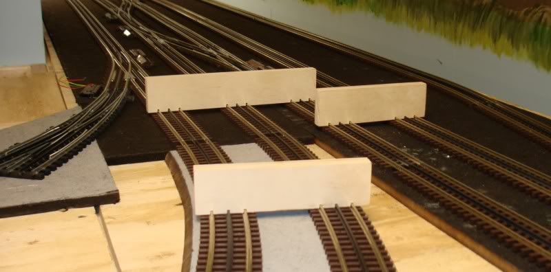
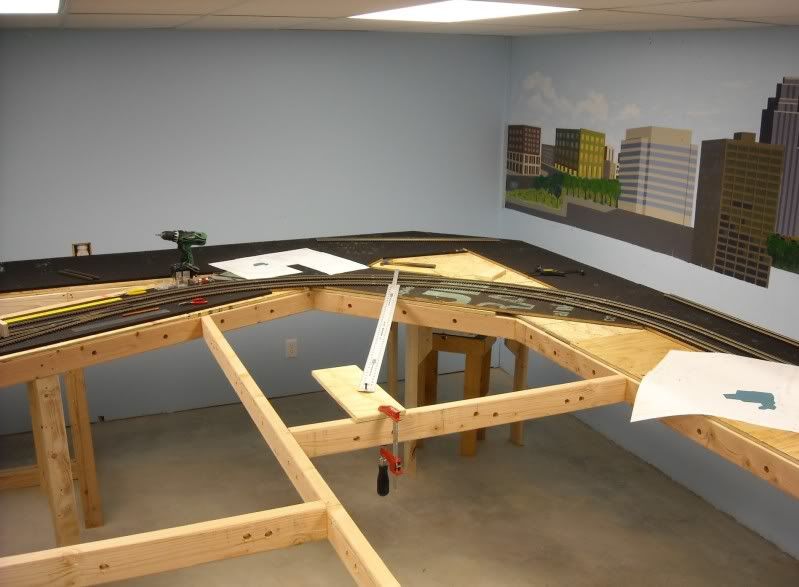
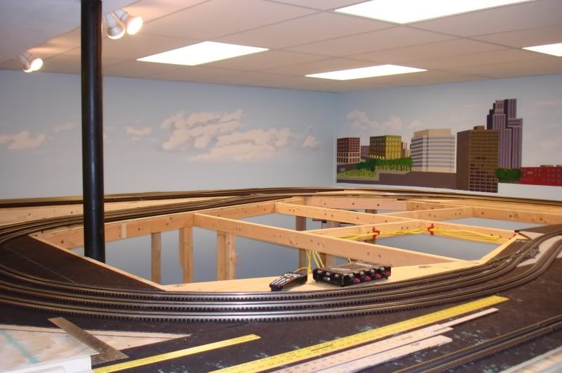
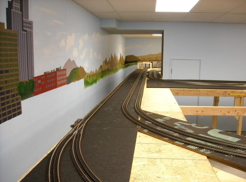
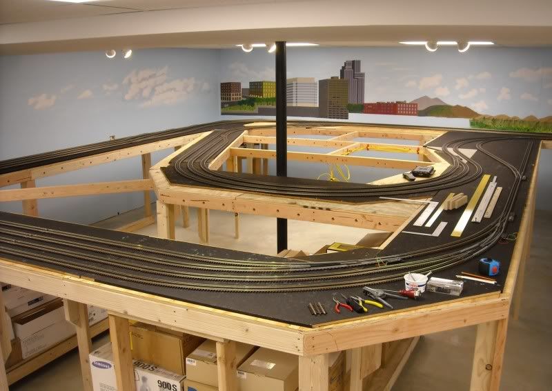
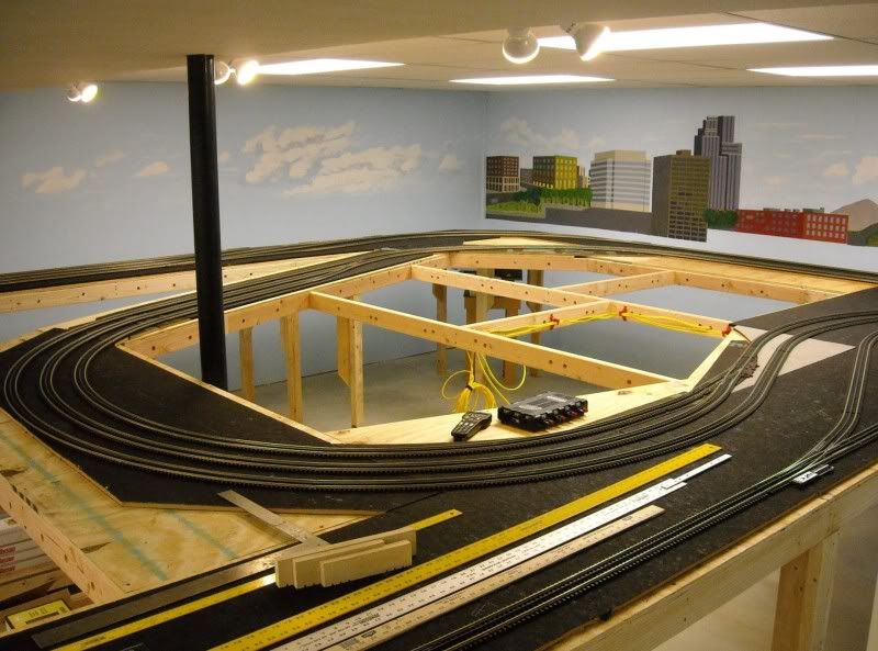
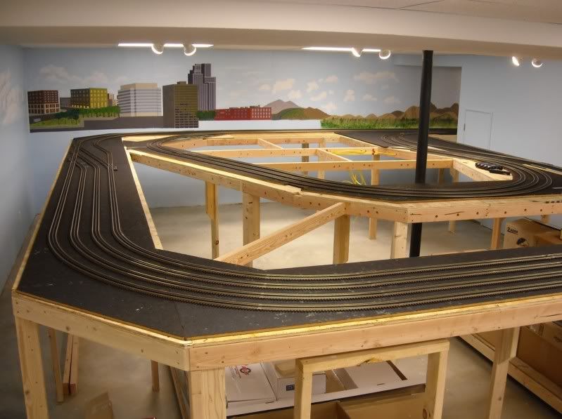
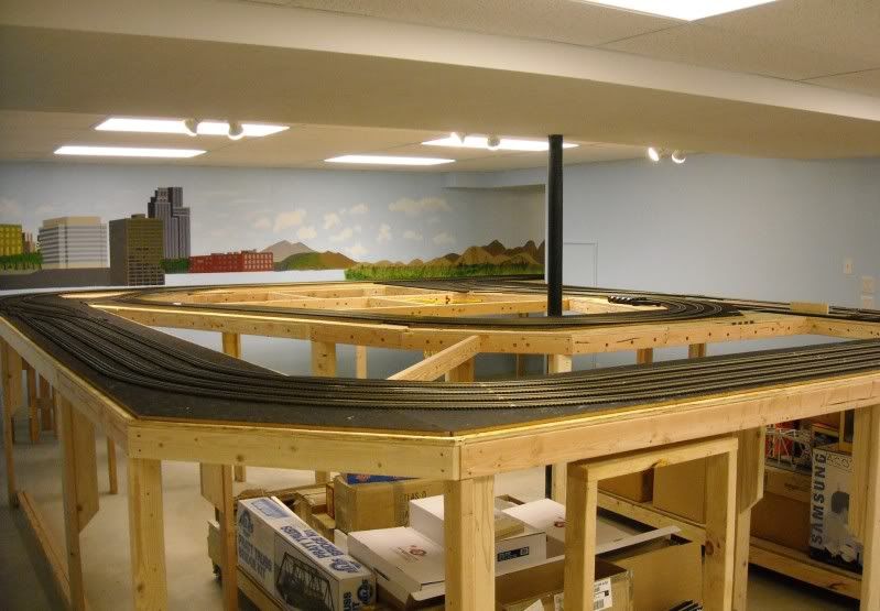
Progress is somewhat slow, but not for lack of trying. The way I designed the layout requires a lot of cut straight and curved track sections, and I am spending quite a bit of time with the cutoff wheel and the file. Anyway, here are some pictures.

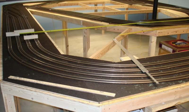
Some of the track at Etieca Valley as seen when standing on an 18” platform.


Track that will connect the West and East sides.


City Backdrop: I paint some every week end, but I find this somewhat difficult.


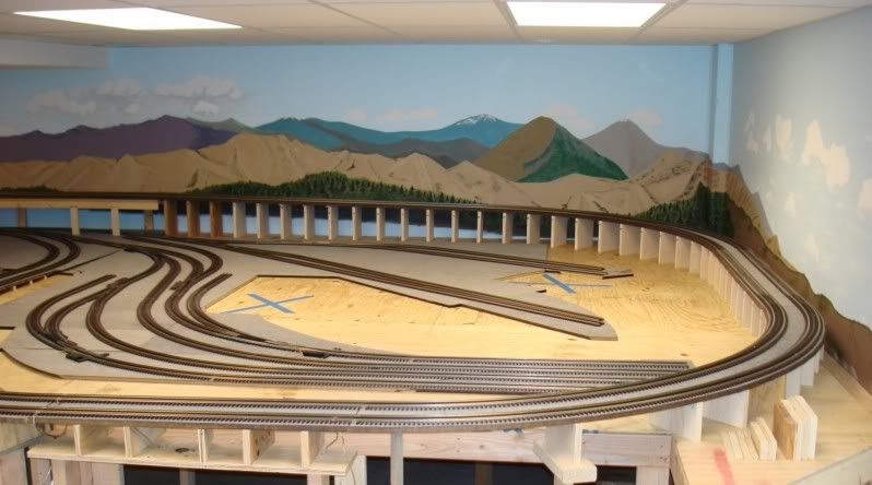
This portion of track will be supported by a wooden trestle. It will span nine feet, with a 30” bridge under the straight track section. I will build the trestle from scratch and will post pictures soon.


Track gauges, as posted by Don (DMASSO). These are great and really help lay track easily and accurately. I made one for three tracks and two for two tracks, as shown, and have been using them with great results.


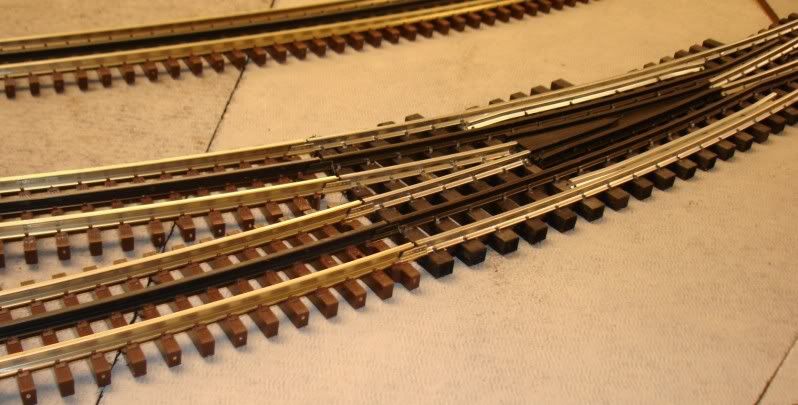
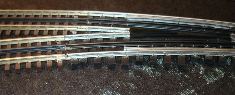
To join Ross Custom switches to the Atlas track, I simply cutoff one end of the standard Atlas track joiner so it is flush instead of having the protruding lower end. This allows the joiner to engage more of the RCS rail.


Back soon, and thank you for looking!

Alex
Jack,

As follow up to Don's reply -
I used a 60-tooth, thin kerf Freud blade (10" table saw). The slots are a slip-fit (snug) on the rails, so you have to get the distances just right. You can use an 1/8" kerf blade, I imagine, and have a little looser fit, and it wouldn't hurt.

I used 4-1/2" center distance since that is my curve spacings (Ø108-Ø99), but you can make your gauges to fit your spacing, as Don mentioned above.

Alex
It has been a while since my last update, but I have been making some progress. Besides track laying, I also upgraded my DCS TIU’s to the latest software, and even ran some trains! I had a new MTH F3 ABA Santa Fe and passenger car set, and also an MTH Big Boy that I had received for my birthday and Christmas and had never run. They are fantastic!

Anyway, I am about done with the lower level track; just need to do one section that will not take long. Here are some pictures that you may enjoy.

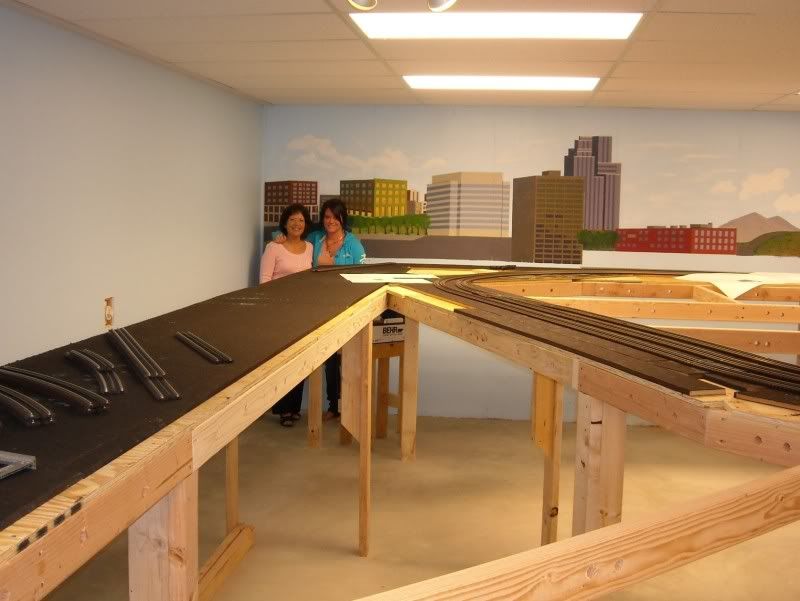
My wife and my granddaughter just before I started laying track at this end.


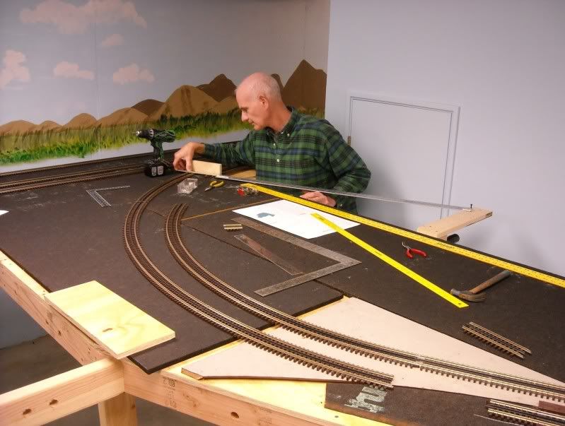
I found that the RR-Track layouts are very precise and if the tracks are cut and laid accurately, they will match the RR-Track perfectly. One of the tricks is to establish the proper radius for the curves. Even when using sectional track as I am using, if the centers are not established, the tracks can be off considerably. Here are some examples from this last track laying session.

My granddaughter took this picture standing on a stool while I was checking some curves.


Other centers:


Trying my hand at painting clouds of the stormy variety.


The tracks that connects the two main areas.


Bird’s Eye views


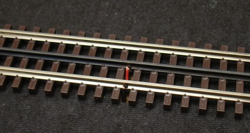
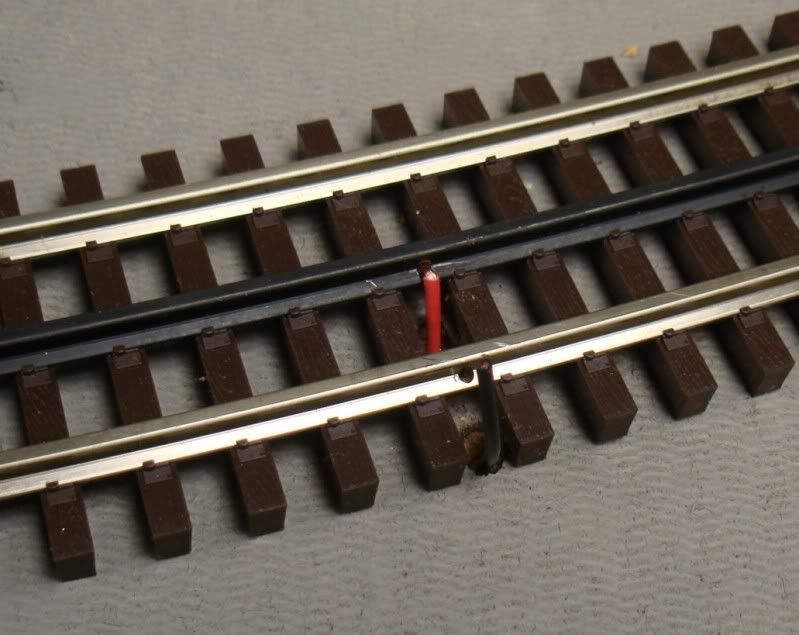
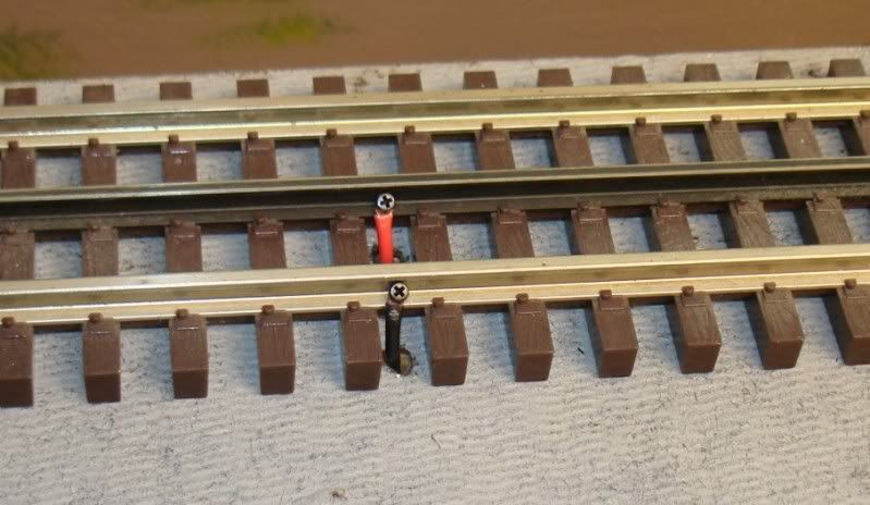
My now favorite way of connecting the wires to the track (extremely easy to do)


Overall at Eye Level


I’ll be back soon with more pictures. Thank you for looking!

Alex
Alex,

Looks great so far! Keep the updates coming!

I was wondering how you like your decision to go with the ross switches and the Atlas track. I just started ordering Atlas track, and am still up in the air over the switches. I guess the only reason not to use Ross, would be because the ties look so much larger than on the Atlas track? What were your thoughts on that?

Also you posted above "My now favorite way of connecting wires to track." What exactly are you doing there?

Keep up the great work!
Zett,

No problem installing or mating the Ross switches with the Atlas track or switches. Here are some examples using plastic rail joiners and also the regular Atlas joiners. When using the latter, I cut off about 1/8” from one end of the joiner with the cut off wheel because the exposed Ross switch rails are short. But the joiners fit just perfectly of the Ross rails.


My concern is that none the DZ machines have worked as I would expect – at least not yet. I test every Atlas and Ross switch before installing them, and so far none of the over 30 Atlas switches I have used so far has malfunctioned.

But not a single one of the eight Ross switches I have used up to now (all curved, BTW) has worked as I think they should. The switches themselves (without the DZ machines) are fine – they operate freely. But the machine does not throw all the way consistently even when not on the switch! That is, instead of traveling fully (from one end of the crescent shaped slot to the other) they are shy about 1/16 to 1/8 inch. I have tried 14v and 20v, and the result is the same. I have also added two or three drops of fine oil as has been recommended, but that has not helped so far.

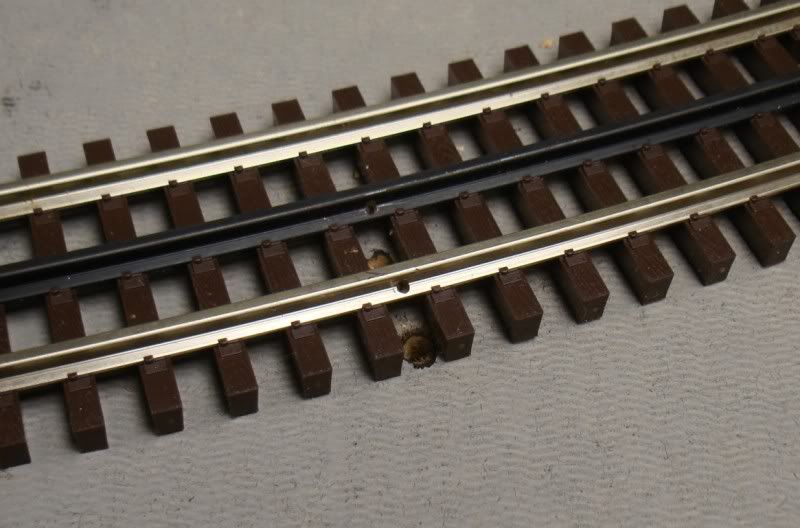
As far as my favorite way of connecting the wires to the rails, for the full story look at this thread:"Screw It!" – but you can get the idea with these three pictures:


After trying several #0 sheet metal screws, (Button Socket Head, Slotted Pan Head, and Phillips Pan Head) I have settled on the #0 x 1/4" Pan Head Phillips Sheet Metal Screw, Black Oxide.

Thank you for looking.

Patrick. Am I excited yet? You got that right! When I finally ran a train last week, even though it was only over 40 or 50 feet of track, I was beyond myself. Thanks!

Alex
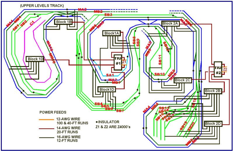
Here is my wiring scheme (track power only) as of now – it will change!
• Two Z4000’s to two TIU’s. (12 AWG wires. Two about 100-ft, two about 400-ft)
• TIU’s fixed and variable inputs jumpered to provide four output channel s.
• Four output channels from each TIU to four terminal blocks for a total of eight terminal blocks. (14 AWG wires, each about 20-ft long) Some of these will be relay controlled to cut power off to selected track blocks.
• Eight terminal blocks power up to six track blocks. (16 AWG wires, each about 12-ft long)

The wiring diagram:


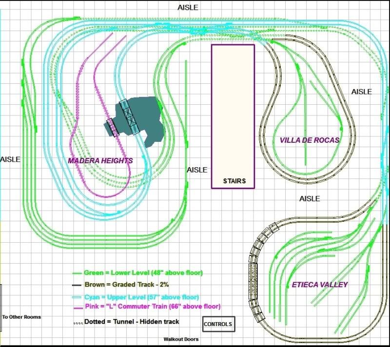
The track layout


Alex
Last edited by Ingeniero No1
Don,

I mounted (late last night) the TIU's pretty close to where they are shown in the wiring diagram. Looking at the RR-Track layout, TIU No. 1 is just under the small bridge over the lake above the "Madera Heights" name, and TIU No. 2 just to the right of the word "Aisle" on the right of "Villa de Rocas".

The two Z4000's will be where [CONTROLS] is, at the bottom of the diagram, to the left of "Etieca Valley".

I hope to install a couple of terminal blocks tonight, but I am making these with terminal strips that I had from previous HO layouts and is taking a little time. Also, I can find only two of the magic bulbs of the 10 I bought three years ago, so I just had to order some more. (Well, at least I won't be moving again and misplacing things.)

And Thanks again.


Alex
It has been a while since I update my progress, but believe me – I have been working on my layout!

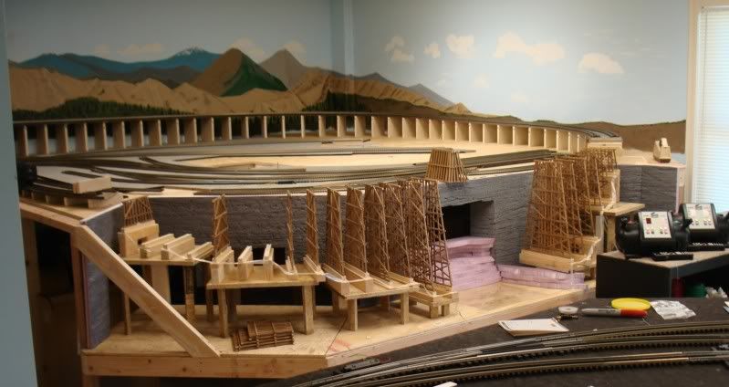
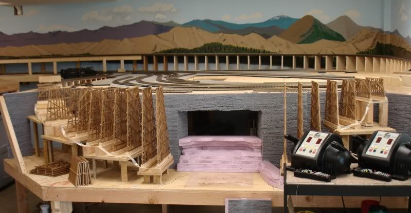
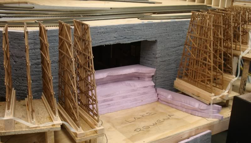
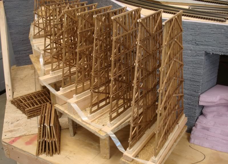
I worked on the DCS system for a few days, laid more track, and then started on the trestle. Since I could not find the type of prebuilt bents I wanted, I decided to go from scratch. I downloaded a lot of information on full-scale as well as model trestle design, and came up with what I wanted.

Instead of buying all the ‘lumber’ already to size, I cut my own 1/4-inch square pieces from 6-inch wide x 24-inch and 36-inch long poplar stock from HD and Lowe’s. The smaller stuff is Midwest basswood that I bought from Tower Hobbies.

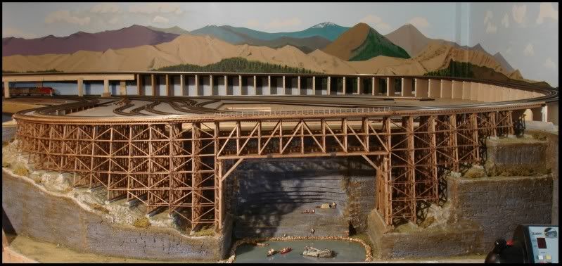
The Judy Jane Trestle at Etieca Gorge over Lake Rowena is 10-feet 4-inches long (496’ FS), its average height over the lake is 25-7/8 inches and it is on a 2% grade. It supports the dual-main track, and will consist of 29 bents ranging in height from 4-13/16 to 19-9/16 inches. Each bent has 10, 1/4-inch square posts (12” square FS) of varying lengths, and a number of horizontal (sill) and diagonal (sway) bracing depending on height. The mud sills are 1/4 x 3/8-inch as I have grooved the piers 1/8-inch for better stability and alignment, so they will protrude 1/4-inch and appear to be 1/4-inch square.

The center portion of the bridge, over the lake, will not have bents that extend to the ground. Instead, those bents will be 6-1/4 inches long and rest upon heavier lumber.

After much deliberating and reading, I decided to make the sway braces out of 1/16 x 1/4-inch (basswood), as many full-scale trestles use this size (3” x 12”) lumber. Other lumber will be 1/8-inch square (6” x 6” FS) and 1/16 x 3/16-inch (3” x 9” FS). Altogether there will be around 2,000 sticks.

I have all the bents finished except I ran out of ‘lumber’ for the sway braces for the last 12 bents; the shorter ones. I will finish them this week. My wife Judy, after who I named the trestle, stained all the ‘sticks’ and has built a handful of bents. I’ll post specific details of construction soon.

Here are some pictures:
(Some of the bents in place but not glued yet as I have to finish the 'rock walls' first.)


Thank you for looking!

Alex

PS. The pink foam was an after thought (thanks, Patrick) and I ran out. Had only bought one 4x8' sheet to try it, liked it, and will continue using it. Will buy more tomorrow.
quote:
Originally posted by Tom Tee:
Humm..........enough wire to fill a gutter Eek..........Maybe go look again at Ed R's "They said it could not be done" thread on the 2 rail side.


...I like Rich's idea a lot better, but the gutter is hidden by the velcro skirt, and the wire is very accessible. The described layout was two-rail with a very sophisticated electrical command and control system started before the invention of DCC in HO. The control room had an electronic wall displaying the position of every train and every turnout on a 2400 sq. ft. layout. Lots of wire, and many members with very sophisticated computer and electronic backgrounds. The gutter was great, because you could modify a 70' wire by just reaching into the gutter, and locating and servicing that individual wire.

Alex, your layout is exceptional. Thanks for the photos! Cool

Cordially,

Dennis
Don, Dennis, Rich -

Thanks! Fun to post some of the work.

Had I found the type of trestle bents I wanted, I would have bought them instead of building them from scratch. Is not that they are not fun to build; they are. But they do take a lot of time.

The calculation of the bent heights, and the height of the piers and bases, combined with the 2% grade, and their location on a curve, was somewhat challenging. But once I had the XL spreadsheet done, it was a matter of cutting sticks and spacers to match the calculated heights; and measuring the spacing between the inner and outer bent cap ends for proper location.

Alex
Alex,

Looks awesome!

I really like your benchwork leg design.

It looks like the main leg determines the height.

I have two questions:

1. Did you do anything special to level the benchwork?

2. After doing the construction do you think that 2x4 is necessary for all the benchwork, or would 1x4 be sufficient for all or part of the framing?

Looking forward to more pictures Big Grin
quote:
Originally posted by StreamLiner01:
Alex,

Looks awesome!

I really like your benchwork leg design.

It looks like the main leg determines the height.

I have two questions:

1. Did you do anything special to level the benchwork?

2. After doing the construction do you think that 2x4 is necessary for all the benchwork, or would 1x4 be sufficient for all or part of the framing?

Looking forward to more pictures Big Grin

Tom,

Thanks.

1. I leveled it as I built it using a 4-ft and a 3-ft level. I cut all the legs the same length, and then used shims as needed.

2. I had always used 1x4'x for the frame of my previous layouts, and they worked fine. I made the legs out of the 1x4's as well, in 'L' shape. I went with the 2x4's this time because the 1x4’s were (are) getting harder to find straight and are more expensive. I used over 100 2x4’s for the layout, which my wife and I hand-picked at Home Depot and had them delivered. (I don’t have a truck.) Going with 2x4’s saved over $100 and allowed me to use the frame pneumatic-nailer. I used a combination of 3-1/2” screws and nails, depending on the joint, and glued all of them as well.

Now that I have the 2x4 frame, I am really glad I went with it. Not only is it very sturdy (I climb on top of it to lay the track and it is A-OK solid and stable), but it does not require as many legs as the 1x4 frame. Also, when it comes to joining two sheets of plywood, I always make the joint or seam fall on a frame member. This is much easier to do when you have a 1-1/2” edge instead of just 3/4".

I will post more pictures soon, and do keep us posted on your progress as well.

Alex
You mentioned how the DZ 1000 switch machines do not always throw the points all the way. I am new to these and mine do the same thing. I have never read of anyone else mentioning this problem on any of the O gauge forums. Currently I have only one loop operationable and it has one switch with the points against the stock rail so I dont worry about it. But soon another loop will be going and it has several switches. I need to buy one more DZ 1000. Should I buy it or something else. Do other peoples DZ 1000 throw the points all the way consistantly? Also you really have to locate Caboose Industries ground throws accurately or they wont throw the points all the way on one side if your off a little.
Dennis San Fernando Valley CA.
quote:
Originally posted by Dennis Rempel:
You mentioned how the DZ 1000 switch machines do not always throw the points all the way. I am new to these and mine do the same thing. I have never read of anyone else mentioning this problem on any of the O gauge forums. . . Dennis San Fernando Valley CA.
Dennis,
Yes, I still have the problem with the Ross switches. I posted this issue a couple of times and the suggestion has been to add a little oil to the DZ machine. I added the oil as indicated, but the problem persists.

NOT ONE OF MY RCS+DZ is working correctly - if by correctly we mean that the DZ machine throws fully each time. Again, the switches by themselves are free - no binding - AND the DZ machines exhibit the same problem by themselves. I have nine of the switches installed so far, have two of them wired so they will automatically throw (non-derail) and they simply do not throw fully most of the time. Sometimes the points throw fully even if the DZ machine does not, but they are not locked in place.

I don't want to start an RCS & DZ rant, but I always read how much better they are than the Atlas, for example. Yet, I have installed over 30 of the Atlas switches, and have not had any problems with any of them. Roll Eyes Go figure!

Maybe someone will chime in?

Thanks for posting Wink

Alex
quote:
Originally posted by DMASSO:
Alex. Have you increase the voltage a bit? . . . Have you tried a bench test to experiment with the voltage?
Hey, Don -
Yes. I bench-test every turnout before I add it to the layout. I use my KW's 14-v and 20-v for the test. Neither the 14-v nor the 20-v makes the DZ advance fully every time. With the 20-v, it looks as though occasionally they bounce back almost to mid point. I don't think that this is an optical illusion, but I have not taken the time to video tape it and then playing it back in slow motion. The Atlas turnouts work fine with 14 volts.

This has raised another issue that I had not faced before (with the HO Atlas turnouts - anyway): How do I know that the turnouts have actuated properly? With the Lionel Fastrack on my last layout, which was only about 7-ft x 20-ft, I could see the lanterns and knew whether they worked properly. (BTW, the Fastrack turnouts ALWAYS worked fine!)

What I am going to do is to place cameras over the areas that I cannot see from the control center. Some of these will be inside tunnels, and others just mounted on the wall and trained on the turnouts. This will be something else to work on AFTER I finish the track and wiring (so I can run trains other than point-to-point).

Thx!

Alex
quote:
Originally posted by Ingeniero No1
............................................................................

NOT ONE OF MY RCS+DZ is working correctly - if by correctly we mean that the DZ machine throws fully each time. Again, the switches by themselves are free - no binding - AND the DZ machines exhibit the same problem by themselves. I have nine of the switches installed so far, have two of them wired so they will automatically throw (non-derail) and they simply do not throw fully most of the time. Sometimes the points throw fully even if the DZ machine does not, but they are not locked in place.
................................................................................

Maybe someone will chime in?

Thanks for posting Wink

Alex


Alex: I have both switch machines. My Atlas switches go back almost ten years. I've done an extensive upgrade with the Atlas 6924 relay boards and 6931 dwarf lights. This added the electric non-derail and power routing I needed to smooth out a lot of electrical holes in a small layout with a lot of switches installed back to back. The 6924 relay boards have also eliminated motor burn out which was common with the Atlas switch motors.

The DZ 1000 are a completely different beast, with a small motor and gear drive assembly. Atlas snap switch are what I term a linear motor with two coils that shuttle the throw mechanics. The DZ switch has a NO/NC Three pole switch that cuts the motor circuit once the throw bar reaches it's limit. There is no adjustment on this limit switch which may be part of the problem. I have quite a few of these switch motors installed on the modular club T module. They can be problematic as you have described. I oiled, tightened, and loosened the screws several times and am operating at a 18 volts AC. Still there are some glitches.

Note the green limit switch in the two throw positions. Most likely it is cutting out before the throw is complete. At least that is the way my switches seem to work. I very seldom ever see the manual throw bar on top of the switch all the way left/right.


My thought is send them back until you get one's that work properly.
Mike

Alex Thanks You have really put a lot of effort into showing this forum what it takes to put a top notched layout together. That's time you could have easily used to advance your project.
Much appreciated and Thanks Again
Mike.
Mike,
I just read your post, above. I did not suspect that the DZ1000's were like that at all! I thought that they were of the dual-coil/solenoid variety.

Now that I see your excellent, fine detail pictures, I will look a little further, and post what I find, which I expect to be the same as what you just said. Wink

You also said, " I very seldom ever see the manual throw bar on top of the switch all the way left/right."

And do they work OK that way for you?


THANK YOU!!!!


Alex
quote:
Originally posted by Ingeniero No1:
Mike,
...............................................................................

You also said, " I very seldom ever see the manual throw bar on top of the switch all the way left/right."

And do they work OK that way for you?


THANK YOU!!!!

They do work, on occassion they will hang-up. Most of these switches are paired cross-overs, with two throws at once. That may effect performance. There are two throw buttons per switch set, one on either side of the module, along with a Lionel SC-2 control. Switches pictures are Ross 204 three-ways

Finish paint


Alex

Add Reply

Post
The Track Planning and Layout Design Forum is sponsored by

AN OGR FORUM CHARTER SPONSOR
×
×
×
×
Link copied to your clipboard.
×
×