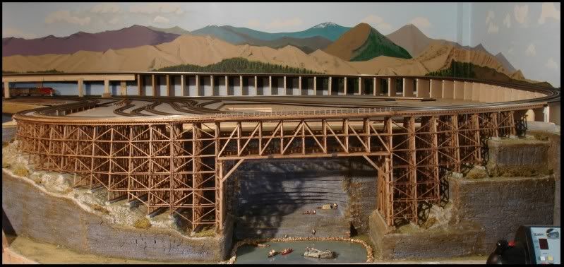
Alex,  Glad you have resumed posting your enhancements to the layout. I followed your progress during the early stages of construction which I found to be extraordinary and very informative.

Concerning your latest post on using relay modules to control power to remote blocks. Do you use LED's on your control panel to indicate block status and how do you connect them to the toggle switches?

Gerry

Great Thread  - love to read the updates

Thanks!

Mike, regarding the 5vDC supply - As I said, above, if you have 12vDC available, or even 24vDC, you can 'buck' the higher voltage down to just about any level you desire. I just used one of these Buck-Step-Down modules for my new Menards American Power & Light building, which requires 4.5vDC. This little unit, priced at $2.45 and minimal S&H, has a three digit display that allows you to see the input voltage, the output voltage, and can be used to calibrate both the input and output! It can handle 2 amps, which is more than enough for many of our train applications.

The 3-digit display can be turned off . . .

AmrPwr DC supply 1 IMG_1711

- - - or turned on to display the input voltage (12.2v in this case - hard to read in the picture, but very plain in real)

AmrPwr DC supply 2 IMG_1710

--- or turned on to display the output voltage (4.5 in this case)

AmrPwr DC supply 3 IMG_1709

Very easy to use. I ordered five and the small S&H covered all five.

Alex

Attachments

Images (3)
  • AmrPwr DC supply 1 IMG_1711
  • AmrPwr DC supply 2 IMG_1710
  • AmrPwr DC supply 3 IMG_1709
Last edited by Ingeniero No1
SGMret posted:

Alex,  Glad you have resumed posting your enhancements to the layout. I followed your progress during the early stages of construction which I found to be extraordinary and very informative.

Concerning your latest post on using relay modules to control power to remote blocks. Do you use LED's on your control panel to indicate block status and how do you connect them to the toggle switches?

Gerry

Hi Gerry,

I was going to have LED's to indicate the ON/OFF status of the various track blocks, but with LED's already at every turnout to indicate Normal or Reverse position, and toggles at the tracks to turn them (the tracks) ON/OFF, I thought it would be too crowded and perhaps confusing. So I did not use use LED's for this, but instead just look at the position of the toggles: Toggle Up = ON, Toggel Down = OFF, and it works fine. 

To actuate the relays. From the 12vDC supply, I connect all the toggles common contacts to the +12v of the supply, and the -12v goes to one side of the relay coils. The other contact sides of the toggles go to the individual relays. Like this:

Relay Wiring for Track Control

Thx

Alex

NOTE: In the diagram above, I did not show the flyback diodes I normally add across the relay coils. Since the relays are actuated with toggle switches, the diodes may or may not be necessary, but they never hurt. I did show the diodes in the previous relay module diagram, page 11 of this thread.

Attachments

Images (1)
  • Relay Wiring for Track Control
Last edited by Ingeniero No1

Alex,

I have your posts and refer to them daily.  Your layout is quite beyond belief and one of the best I've ever seen.  Your precision is unmatched.  Also, I am expanding my table layout up two levels and you have already given me several ideas.

Can you please take some time to answer some pretty fundamental questions?  Please forgive me in advance for being so dumb.

1.) How do you get any train to pull 50 cars around curves without them derailing?  Is it the larger radius curves or are they heavier/modified cars?

2.) Can you please explain some of those gorgeous fences:  Did you make them all?  Did you cut all those tiny slats on the wooden ones?Where did you get the chain-link fencing?  Did you make all the track railings yourself?  How did you get them so perfectly aligned? How did you get those post-in-the ground railings to have such straight wires through them?

3.) Where are you getting all those unique figures from?  I've never seen so many different people poses.

I have lots more, but....

Jerry


JerryG posted:

Alex,

I have your posts and refer to them daily.  Your layout is quite beyond belief and one of the best I've ever seen.  Your precision is unmatched.  Also, I am expanding my table layout up two levels and you have already given me several ideas.

Can you please take some time to answer some pretty fundamental questions?  Please forgive me in advance for being so dumb.

1.) How do you get any train to pull 50 cars around curves without them derailing?  Is it the larger radius curves or are they heavier/modified cars?

2.) Can you please explain some of those gorgeous fences:  Did you make them all?  Did you cut all those tiny slats on the wooden ones?Where did you get the chain-link fencing?  Did you make all the track railings yourself?  How did you get them so perfectly aligned? How did you get those post-in-the ground railings to have such straight wires through them?

3.) Where are you getting all those unique figures from?  I've never seen so many different people poses.

I have lots more, but....

Jerry


Hi Jerry! Thanks for your comments -

1) Pulling 50+ cars: As you mentioned, the 1.9% - 2.0% grades and the Ø108" and Ø99" curves must have a lot to do with it. I do not modify the cars, but try to place the heavier ones closer to the locomotives. The Big Boy (MTH and undoubtedly the Lionel VL) has pulled 50+ cars effortlessly, and I know that it could pull more. The MU diesels, whether MTH or Lionel, have also pulled a similar number of cars. I also routinely and successfully push trains with 30 cars up the grades, very slowly. One time, however, while pushing a train with 20 auto-racks plus 10 more cars behind them, one (and only one!) of the auto-racks was pushed out of the way while in the tunnel that is at the end (or start) of the grade. Evidently, the cars behind the outcast car rolled on their own and coupled to the rest of the train. I did not notice this until much later when another train on a parallel track hit the outcast car, and the sound caught my attention. I wondered what had happened, and then saw the car. I had been video tapping all of this, and during playback I was able to see a train with 30 cars, and after the operation, only 29 cars were present. The auto racks are very light.

2) Fences: The wooden slat fences are Model Power (bought) and painted. The chain link fence material is from Dennis Brennan fence kit, which I modified somewhat. The track railings are homemade out of Ø1/4" wooden dowels and Ø0.021" stainless steel wire rope, which would be close to Ø1" in real life. I drill holes through those dowels (after doing a few, it becomes easy), and thread the wire rope. I used the same concept to add rails to the Menards Coil Car:

US Cable FltCar 01 DSC_2344

I then drill holes on the QuietBrace (similar to Homasote) and 'plant' them.

3) Little people: I have several brands, but most are Woodland Scenic Accents figures. And I do have a few Arttista figures as well.

Glad to answer any questions you may have; after all, that is how I learned - by observing and asking in this great forum!

Alex

Attachments

Images (1)
  • US Cable FltCar 01 DSC_2344
Ingeniero No1 posted:
SGMret posted:

Alex,  Glad you have resumed posting your enhancements to the layout. I followed your progress during the early stages of construction which I found to be extraordinary and very informative.

Concerning your latest post on using relay modules to control power to remote blocks. Do you use LED's on your control panel to indicate block status and how do you connect them to the toggle switches?

Gerry

Hi Gerry,

I was going to have LED's to indicate the ON/OFF status of the various track blocks, but with LED's already at every turnout to indicate Normal or Reverse position, and toggles at the tracks to turn them (the tracks) ON/OFF, I thought it would be too crowded and perhaps confusing. So I did not use use LED's for this, but instead just look at the position of the toggles: Toggle Up = ON, Toggel Down = OFF, and it works fine. 

To actuate the relays. From the 12vDC supply, I connect all the toggles common contacts to the +12v of the supply, and the -12v goes to one side of the relay coils. The other contact sides of the toggles go to the individual relays. Like this:

Relay Wiring for Track Control

Thx

Alex

NOTE: In the diagram above, I did not show the flyback diodes I normally add across the relay coils. Since the relays are actuated with toggle switches, the diodes may or may not be necessary, but they never hurt. I did show the diodes in the previous relay module diagram, page 11 of this thread.

Alex,

Could you explain function of flyback diodes you add across the relay coils.

Thanx Gerry

Alex,

Thanks for your answers to my three questions.  Your help is greatly appreciated.

I am going to build a mall scene similar to yours shown on this page.  More questions:

How high are your storefront cutouts?  They look to be 3-4 inches tall.  The size looks perfect and I would like to duplicate the scale.

What paper did you use to get the lights to show through?  I normally use top quality photo paper, but it seems too thick to get light to shine through it.

I will do a row of LED's outside the cutouts, but it looks like you built a backstop of a sort to mount LED's a few inches behind the cutouts. Is that correct?

Finally, what tool(s) did you use to cut the foam arches so smoothly? 

Jerry


JerryG posted:

Alex,

Thanks for your answers to my three questions.  Your help is greatly appreciated.

I am going to build a mall scene similar to yours shown on this page.  More questions:

How high are your storefront cutouts?  They look to be 3-4 inches tall.  The size looks perfect and I would like to duplicate the scale.

They are 4" high x 5" to 6" wide. However, the cutouts to tel the light shine through are smaller to match the 'glass' of the store fronts. See pictures below.

What paper did you use to get the lights to show through?  I normally use top quality photo paper, but it seems too thick to get light to shine through it.

I used regular paper, which proved to be thin enough. BUT, over all the store fronts I used laminating paper, which is shiny, and provides a nice affect.

I will do a row of LED's outside the cutouts, but it looks like you built a backstop of a sort to mount LED's a few inches behind the cutouts. Is that correct?

Yes, see the picture below. Also, I had to dim the LED's in front (added several diodes in series to drop the voltage) as otherwise the LED's would be too bright and not allow the LED's behind to created the effect of a lighted store.

Finally, what tool(s) did you use to cut the foam arches so smoothly? 

Hot wire, primarily, and an X-Acto knife.

Jerry


Hi Jerry,

First, your previous question: "Could you explain function of flyback diodes you add across the relay coils."

A simple explanation: When energized, the relay coil is magnetized, and when its power is shut off, this magnetic field collapses and generates a voltage spike that can be transmitted back to the power source, and this spike can be damaging to some components. The 'flyback' diode, due to the way in which its polarity when it is added to the circuit, does not affect the power applied to the coil; but when the relay is turned off, the voltage spike generated by the collapsed field is of opposite polarity, and the diode acts as a short, sending the spike back through the coil itself (flyback) until the energy is dissipated, which happens almost instantly. Therefore, the diode prevents the potentially harmful spike from causing any damage to other components. Other guys in the forum can probably explain this better than I can, but you should get the general idea.

Here are the pictures mentioned in my interspersed answers in your quote, above. The front LED's that I mentioned are mounted on the inside of the 'concrete' walls and shine on the store fronts. 

HPM 04 StoreFronts1 med crp DSC05111HPM 05 StoreFronts2 med crp DSC05109

Alex

Attachments

Images (2)
  • HPM 04 StoreFronts1 med crp DSC05111
  • HPM 05 StoreFronts2 med crp DSC05109
Last edited by Ingeniero No1

I had wondered about Jerry or Gerry!

Two details I failed to mention regarding how to cut the arches - (1) I cut out a template out of 1/8" plywood to serve as a guide for the hot wire. The template, which I did not throw it away but can't find it or the pictures, is shaped as the inside of the arches, so I just secured it to the pink foam with a couple of coarse drywall screws, and went around it with the hot wire. The only challenge is to keep the wire perpendicular to the foam. (2) The Hot-Wire is from Woodland Scenics. 

Alex

Alex,

Yeah, I spell it with a J so you can distinguish me from who I think is the Sergeant Major.  Thanks again for all your info.  Your talent for detail is amazing.

I have a perfect template to use for the arches.  I hadn't thought to screw it to the foam.  Not sure I'll spring for the $40 to Woodland.  I'll probably wait to see how the mall itself turns out.

Jerry 


Alex,

Thanks for your kind attention.  I decided you are right and ponied up the cash to trainshanty.com, who seemed to have the best price.  I watched a video comparing the options, and this clearly made the most precise cuts.  One question, have you ever had to replace the wire for your Woodlands unit?

Jerry

Ingeniero No1 posted:
It has been a while since I updated, and that is because I have been busy building the trestle - remember? I named it the Judy Jane Trestle since my wife has really been helping me all along both finishing the basement, and now the layout.


More pictures here here: Judy Jane Trestle

Alex

Alex

When I click on Judy Jane Trestle it takes me to OGR's homepage. Is it supposed to do that? I would think that a hyperlink would take you directly to something. Help me figure this out please.

Mike

Ingeniero No1 posted:

Mike,

I need to look into this.  I am not on my own computer now, but will be in a couple of days, and will let you know.

Alex

Don't mean to butt in Alex., but that post appears to be from 2011 and I think you might have been trying to take us back to earlier photos of your progress on the trestle here. The link probably worked back then, but references might have changed somewhere along the way.

mknight1957 posted:

Thank You DoubleDaz,

Is there an archives where his photos might be so I could look at them?

Mike

Not that I know of. There is the Video Clips menu option, but AFAIK members have to specifically upload videos and photos there and not many do. I tried using the Advanced Search option to find Photos posted by Alex, but didn't get any results.

JerryG posted:

Alex,

Thanks for your kind attention.  I decided you are right and ponied up the cash to trainshanty.com, who seemed to have the best price.  I watched a video comparing the options, and this clearly made the most precise cuts.  One question, have you ever had to replace the wire for your Woodlands unit?

Jerry

Hi Jerry,

Better late than never?

No, I have never had to replace the nichrome wire that the cutter uses to cut through the foam. I bought a spare, which has enough wire for three replacements, but have used it.

Alex

DoubleDAZ posted:
mknight1957 posted:

Thank You DoubleDaz,

Is there an archives where his photos might be so I could look at them?

Mike

Not that I know of. There is the Video Clips menu option, but AFAIK members have to specifically upload videos and photos there and not many do. I tried using the Advanced Search option to find Photos posted by Alex, but didn't get any results.

Dave, Mike -

I have tried three times, with searches and a lot of reading, to figure out to where that link should have taken us, but have not found anything. I suspect that that mysterious link was to additional construction pictures, of which I have a lot that were not in the magazine article and were never posted, and will assemble a new post with to include those. 

Thx!

Alex

My photos were taken off by because I am in the process of maybe being published in another magazine.  So they asked not to show any photos until after. Now hopefully I will get pubilshed soon if I do I will put the photos back on if I don't I will put the photos back on. My son and I are excited so we hope this doesn't take to long not bad for two novices. 

Mike 

pennsynut posted:

I can't believe I have missed this thread over all these years you have been working on your layout.  It's probably my age and I have been a little busy trying to copy great ideas from all the artists on the forum. In any event, wonderful work.  

The same thing happens to me. Every once in a while I find a new-to-me thread that is several pages long, about a great project or layout, which somehow I had missed. Glad you found it!

Alex

Alex, I am just getting started reading about your layout, and from page 1 through today, page 12, it’s an amazing Journey with a beautifully executed plan of action. I have not found the video’s yet but your attention to great construction and your track work is meticulous. I look forward to reading more about your layout. Thank you for posting your layout for our education as your ideas are novel. We learn from others in the hobby, Gunrunner John, who has a new layout in a progressive stage, and Mike G, with layout work in progress, Farmerjohn in Ken, and so many others, it’s simply fun to read all about there work.  One thing for sure, your hanging Millhouse turntable is a super idea,....Wow.  Keep posting, we’ll keep reading about your “Hidden Pass Junction RR”,  model railroad.  Happy Railroading 

Last edited by leapinlarry

Hello one and all!

I haven't posted in a while, but not due to lack of interest - just other 'distractions'.

Anyone in this forum is more than welcome to visit and take a peek at the layout; just drop me an email or message. We live about a mile and a half south of I-70 exit 200; about 50 miles west of downtown St Louis.

Thx!

Alex

PS. You can access my YouTube videos at my channel: 03patines (that is zero-three). Note that some of the train videos are from my first layout; I started work on my present layout, the Hidden Pass Junction RR in Feb 2011. Started running a few months later, and by summer 2012 all the track and most of the wiring were done and operational. I have added a couple of spurs since then, and lots of buildings and scenery in the last three years. As of the end of 2018, I was close to 27,000 feet of wire for the track power and control, lighting, accessories, and switch-track operation and detectors.

Last edited by Ingeniero No1

Really nice job Alex.  I've been here before because i remember that cool bridge & the hatches.  I'm planning on going back and reading thru all the posts from beginning to present.  Lots of great ideas and info here.  I understand how much time is involved in taking on a project like yours.  I'm all excited to get ours started when these travel restrictions are lifted.  I live in Steubenville OH. The layout is at my son's house near Atlanta, so my update posts will be months apart. Hoping in June to finish the wall wiring and plugs, get the drop ceiling and lighting done, and lay the vinyl floor.  Then late summer install drywall and build the two false walls. That should get us ready to begin table construction at Christmas (I hope).  BTW, My nephew lives near Scott AFB. If i ever get a chance to get down to see him, i'd love to see your layout in person.  Thanks for sharing the posts and pics of your layout.  I'll be back with questions.   

Add Reply

Post
The Track Planning and Layout Design Forum is sponsored by

AN OGR FORUM CHARTER SPONSOR
×
×
×
×
Link copied to your clipboard.
×
×