Q1. No, the length of the insulated rail section does not matter. Even for a mile-long (!) section, when the consist first enters the section you have only 1 axles, then 2 axles, then 3 axles, etc.. straddling the outer rails and providing the electrical trigger signal. Likewise, when the consist exits the section you get to the point where you have 3 axles, then 2 axles, then 1 axle, then 0 axles. In both cases (entering and exiting) there is the opportunity for an intermittent electrical contact which would create a false trigger.
Q2. I may be misunderstanding you question. But in the case of the timer-relay module, the trigger signal from the insulated rail section does NOT directly drive the relay coil. There is electronics in the relay module which, in effect, disconnects the trigger signal from the relay coil after the programmed interval (say, 1 second) has elapsed. So even if the consist stops on the trigger section providing a continuous trigger, the relay only turned ON once for 1 second.
So here we have one module in action. The painted white track section is the insulated rail section. There is a white wire going into the timer module. This obviously shows half of what would be needed using the 2-diode method discussed earlier.
Initially there is NO resistor-capacitor filter. Note how there are a couple of "false triggers" where the relay turns ON (listen for the relay click on and off coincident with the digital timer counting down from 1.0 sec). Note also how even after the relay turns on and off, the "consist" can sit on the insulated section and you get no additional triggers. But from dirty wheels, track, etc.. you can get false triggers from a momentary loss of a solid electrical connection between the outer rails.
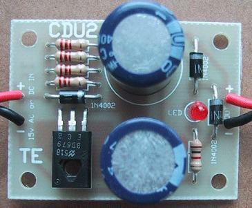
Addendum: And here are some photos of components used.

If you have a stash of DC-output wall-warts pretty much any would probably work. 9V and 12V are common DC outputs. The timer module suggested can handle anything between 6-30V. Shown in above recycled photo is an output adapter connector which converts the common coaxial barrel of a wall-wart to screw-terminal so you don't have to splice into the wall-wart cable. This photo was from this OGR thread which also included the following photo:

In the earlier thread I suggested buying a resistor kit which gives you a broad assortment of resistors for less than a penny a piece. Even if this is your only venture into component-level assembly, it shouldn't break the bank!
And here's a photo of the Delay-OFF relay module. Note that I only show photos since OGR does not allow direct eBay links. And even eBay listing #'s which can help to find a current listing go stale after 6 months or something like that. I'm thinking this application may come up again!

This one seems to be the least expensive when you buy 2 since shipping is apparently the same. Otherwise there a plenty of eBay sellers for about $3 each with free shipping from Asia.
If you do choose this route, it can be confusing to "program" the timer module to what you want but I'll be here to help if you get to that point! Many of the instruction sheets that accompany these modules are poor translations to say the least!
And if you need those 2 diodes per the diagram that cjack posted, they are a couple pennies each:


