Replies sorted oldest to newest
That's awesome! I'm thoroughly impressed. Does this solve a section of your track plan that you couldn't solve with standard track ?
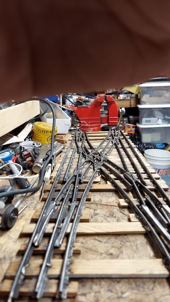
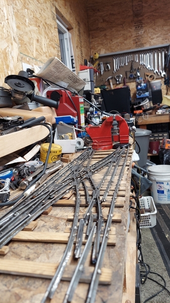
It could be solved for about $400 by buying Ross switches. I don't have that kind of budget. Tubular is cheap. It can be hacked, soldered, and bent to whatever you need.
This is a #60 trolley. Worst case for contact
Attachments
Looks like you don't have any dead spots. That's pretty cool. Gotta admit, I never thought about just building my own fancy tracks.
It's a little involved. I use 1/4" steel plate cut for the frogs. They are cut with a death wheel by hand. The points are ground with a death wheel from 1/4" key stock. Buy it in 12" lengths in bulk. Drill and tap for 6/32 thread screws to attach to small drilled steel plates soldered to the rails. I use hardwood for all critical ties. I cut and bend copper "U" staples that are drilled through the ties with a dremel and then soldered to hold gauge alignment. A fixed wheelset confirms the gauge before soldering. No limitations for fitting the space or track spacing. Custom built for the location. I built a custom rail bending jig for 027 track to increase the radius on a ceiling layout.
That is one awesome job although it may be beyond my DIY skillset. Tubular turnouts look so much better without the oversized black bases. Because I don't know, what is a death wheel?
Also write up an article about the build, it would make a great addition to the magazine.
@necrails posted:That is one awesome job although it may be beyond my DIY skillset. Tubular turnouts look so much better without the oversized black bases. Because I don't know, what is a death wheel?
Also write up an article about the build, it would make a great addition to the magazine.
Hand-held grinder. Wheels have been known to fly off......do a youtube search and you'll never touch one again.

Attachments
@Empirical Builder posted:
This is very impressive. Lot's of details.
The rails looks much better without the plastic bases.
Bob
@Empirical Builder posted:This is a #60 trolley. Worst case for contact
I will just say……WOW!!!
Background. Inherited Dad's trains. Every year put under Christmas tree for kids. Then put away. I wanted to display or run them year round. Real estate for a full size layout was not available. Hence, a ceiling layout in rhe basement. Out of the way, cats don't bother it, and a room size layout can be had. Could also use wider curves then standard 027 track. Hmm. Wider track radii sells for a premium. But I got a box of of 027 track for $40. Hmm. I have a HF 7 x 10 mini lathe and a cheap HF drill press. Surely there must be a way.... the rail roller came about. Take small radii curves or straights and change them to large radii. And yes, my shop is a mess. Work in progress...


Attachments
Basic construction and tools. Basic drills and taps. A table saw to rip ties. A Weller D550 iron to solder rails in place. Some 1/4" steel plate. Use a hacksaw or Sawzall to cut out frogs. Angle grind the flangeways in a vise. Some sheet metal scraps and scrap nails to connect rails and points. Some copper wire for "U "shaped spikes. Drill the ties with a Dremel tool with a 1/16" bit. Solder rails in place at best alignment. Use 1/4" keyway stock for angle grinding switchpoints. Various screwdrivers, pliers and a scribe comes in handy at times.
Left to do on this project: Add guardrails to frogs and crossings. Amazing that I don't seem to get derailments. Drill switchpoint ends and attach some nonconductive throwbars; using screws or rivets. The rails not being used are converted to the center rail for power, so no loss of electrical contact; as the trolley proves. Wiring of relays and/or components to switch them in pairs and correctly reroute the power. Design of screw drive switch machines. Final grind of points and frogs with Dremel to fine tune; probably after installation when a full size train is running through them. Add signaling for appearance and protection of blocks. It is never done....the beauty of this hobby!
Attachments
I'm really impressed. I will have to make my own crossings for two spots on my layout and I feel more confident about it now. I have the tools you mentioned. Sounds like I just need to dive in and give it a shot.
Nice work and ingenuity on making your own tooling and thinking outside the box!
Yes, Bill. The thing to watch with all metal crossings is that the outside diamond rails switch from being from ground to center rail polarity depending on the direction of travel through it. You can leave them insulated for a dead zone or have circuitry to switch them depending on the route. I am sure you know the center roller can't touch a live outside rail. Kind of how I want the switches to operate. By switching the unused route to the appropriate polarity to leave no dead spots. I power mine with DC, but the same relationship holds for AC power as well.
Attachments
I experimented with several designs and modifications to improve and simplify the construction. A couple of videos using the 100 year old switches that I repaired. Learned some valuable lessons with them.
Update: Got some throwbars installed. One is oak, the rest are masonite. Broke my 1/16" drillbit in a switchpoint so switched to 5/64"; as it is stouter. Use nails of about 0.08" and drive them in from below. Cut them just above flush to the switchpoint, grind down slightly with a dremel and flatten with a punch on a block of steel to make "rivets" to keep them in. Design of a switch machine. For $13, I found these on Amazon, and will try to cobble up a screw drive with a plate attached to the throwbar, and 6/32 screw/nut assembly. Need to make contact sets for length of travel and power routing. Might use cheap limit switches for that. Pic will show the underside and how the U-shaped copper wires are drilled, recessed in the ties and soldered to the rails. Sorry that updates are sporadic. I had some recent health issues and am back to working full time again. Unfortunately, this is just a hobby, and not my job!


