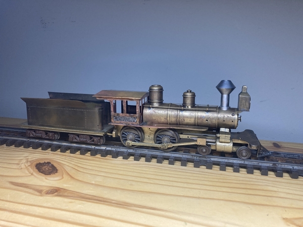
Well it's been a while since I posted, but I've made some progress. In my last post I mentioned I wanted to shorten the tender and figure out how to power the loco, and I think I've got it figured out now.
To start on the tender, I desoldered the old mounting plates from the tender shell, and then annealed and flattened it to prepare for reshaping and shortening.


I proceeded to clean up the metal, and I created two scribe lines just outside the rivets, and cut it down to that line, so the entire tank is vertically shorter. I then had a jig with the right curves 3D printed so I could form the shell into a better shape. Originally the rear corners were square, but I formed them with a 1/8" radius, and the front with a 1/4" radius.

After shortening the tank, I decided the entire tender was simply too long, so I cut about 1/4" out of the middle of the frame and soldered it back together shorter. Unfortunately this means that the Pittman can motor I mentioned previously would no longer fit, but I'd prefer an open frame motor regardless.

Upon reassembly, I'm very happy with the new proportions - much better than it was.

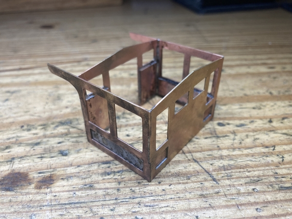
Since the rear corners were now radiused, the tender boards needed to be radiused as well. The math and scribe lines were a little difficult, but I got there in the end.

Before I made the boards, I soldered in the top plate for the tender, which was fairly difficult to keep the plate fully lined up with the shell. I didn't want to re-do that solder joint again, so I decided to rivet the boards in plate, with a little added solder between the seams. I also fabricated a water hatch for the tank and a little bracket to hold the brake wheel.

And back to the loco, I revisited the bell. I was able to reuse the old stand, but I had to fabricate a new yoke.

I also got the front coupler link finished and installed, and while I don't have any link and pin cars, it's functional. I decided to trim off the taper that was on either side of the pilot, giving it straight sides. You can see in this photo how wide the slide valves are - at some point I intend to cut both off and relocate them further inboard.

I also found that a Pittman DC81 fit inside the tender very well, so I fabricated brackets to hold it in just the right position and angle.

And I was able to fit a NWSL gearbox between the rear drivers. Unfortunately, due to the pressed on drive gear, I had to cut slots in the frame so the rear axle could be removed, so I fabricated a couple brass plates to hold the axle in place.

And I found a small silicone tube that's flexible enough to handle the job. It's not suitable for stronger motors, but works well for this little engine. It's not visible, but I had to add a little brass link from one of the screw holes of the gearbox to the loco frame to hold the gearbox at a suitable angle, otherwise it wanted to flex up and down. After quite a bit of fine tuning, the motor and gearbox drive it along very well, and it can pull a few cars easily.

And finally a photo as she sits today - a much finer model than she was back in '49. Lot of work left to do, but I'm very happy with my progress so far.