I have recently jumped into the MTH world in the past year and I’m starting to put my own touch on a few steamers.  I picked up a few later ps2 engines with the wireless draw bar and my biggest gripe with the entire mth steam fleet is the drawbars.   Particularly the length.  I understand the necessity but it’s the first thing I tackle is closing the gap.   My problem is I need about 25mm drawbar for these later ps2 engines.   From the best I can tell none this short were offered in 10 pin.  I could easily make my own in regards to the mechanical function however I’m trying to figure out the best way to make the electrical function work.  My first thought was to go back to a tether.    I used a 6pin 25mm bar just to see where it would line up and it 25 is just right.   Just kind of wanted to get your all thoughts and opinions on the situation.   It may seam like a silly thing to do but I really enjoy making small modifications to already great products to make them even better.   Thank you.


Last edited by jeremy ferrell
Original Post

Replies sorted oldest to newest

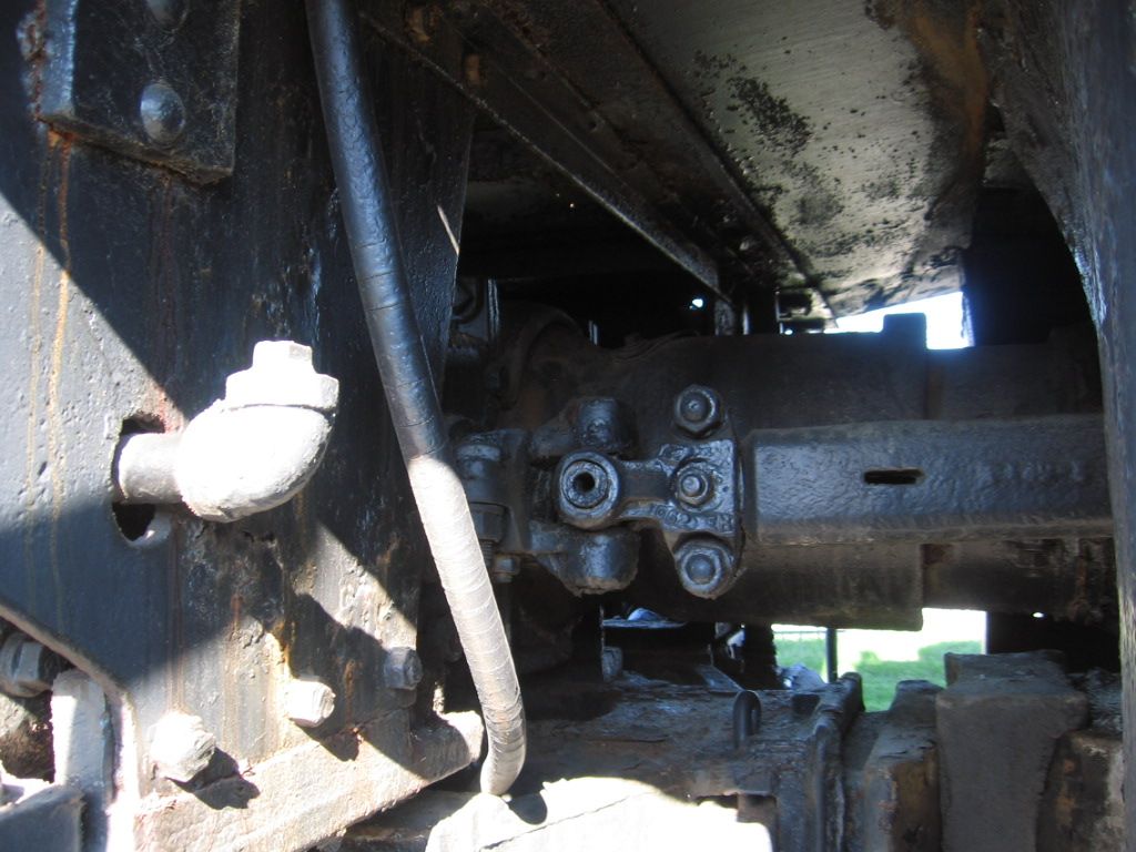
Consider that many steam locomotives had a stoker, which required a pipe/with auger from the tender.  Picture of the Pennsy M1a/b, Railroad Museum of Pennsylvania, Strasburg, PA.   Note the large tube.  The universal joint and drive, in front of the tube, are power for the stoker.   Draw bar lower picture.  Wire tether could easily be modeled as the stoker pipe.  IMO. 

Last edited by Mike CT
gunrunnerjohn posted:

FWIW, it's not a big deal to lay out the PCB for the MTH drawbar of any length.

I would be careful with that generic statement.  Early drawbars had shielding issues that caused erratic ops, and the drawbar traces redone and shielded.  So it is not just a generic print of 6 or 10 traces.  G

Whenever this topic comes up I am interested to see what people are able to accomplish about reducing the gap while maintaining the locomotive as an actual runner.  Please keep us posted.  On the older MTH locomotives, I can usually use the closer hole on the drawbar to close the gap and still run em.  Main sore point on my layout is an 072 to 072 S curve.  I've also noticed that the cab roof corners seem to usually be the issue if you get too tight on the spacing.  

I bought the drawbar kit for my PS3 L2s Mikado.*  I never did change it out though because eyeballing it made me skeptical that it would run on my layout with the shorter drawbar, and I didn't want to cut the ground spring thing to find out.  Does anyone know if that ground spring wire on the PS2 drawbar is actually necessary, or is it just a superfluous ground connection between the engine and tender?**  It seems that both the engine are tender are grounded anyway, and the tender ground wire might just be an extra ground line.  What I am thinking is I will just remove it for the sake of trying the shorter drawbar.  

Anyway, I don't mean to hijack.  Best of luck Jeremy and keep us posted.  

* Edit (9/18/18): I originally said "PS2 L1s Mikado", but I just noticed that it was for my PS3 L2s Mikado.

**Follow up (9/18/18): I checked this by simply pulling the spring ground wire away from the post on my PS2 L1s Mikado, and at least for that locomotive, the power was not cut when I did so.  Therefore, I suspect that at least for this locomotive, at least one wheel on the tender is grounded.

Last edited by pennsy484
GGG posted:
gunrunnerjohn posted:

FWIW, it's not a big deal to lay out the PCB for the MTH drawbar of any length.

I would be careful with that generic statement.  Early drawbars had shielding issues that caused erratic ops, and the drawbar traces redone and shielded.  So it is not just a generic print of 6 or 10 traces.  G

It's still not a huge issue to lay out a PCB, this is not rocket science.  After all, you have a pattern to work with.

Barry Broskowitz posted:

the aim of the light teather 's emitter(s)saturating the light receiver(s) is what's important.

I believe that you may be confusing the MTH wireless drawbar with the Lionel IR tether.

For sure.  It was references to both mechanical and electrical that threw me. I thought "he has no problem with mechanicals" (wiring) and just needed a small shove in the right direction electronically,  

I "shortened" that post some

gunrunnerjohn posted:
GGG posted:
gunrunnerjohn posted:

FWIW, it's not a big deal to lay out the PCB for the MTH drawbar of any length.

I would be careful with that generic statement.  Early drawbars had shielding issues that caused erratic ops, and the drawbar traces redone and shielded.  So it is not just a generic print of 6 or 10 traces.  G

It's still not a huge issue to lay out a PCB, this is not rocket science.  After all, you have a pattern to work with.

is this a project you would take a look at John?   I could send you measurements. Im pretty unfamiliar with boards of any kind but i'll do some research to see what i can come up with on my own.

Get yourself some mil spec double sided copper clad circuit board and cut your own traces. A straight edge and exacto knife plus a drill for the connector holes are all you need. You don't have make a mask and etch it. Make sure its fiberglass epoxy board and not paper or phenolic and it will be strong enough. There are tons of it on the auction sites. 

Pete


Last edited by Norton

You are really brave Pete.  You mess up and let AC bridge a trace to PCB Ground or 5v and a $200+ board becomes junk.  MTH makes drawbars as short as 25mm, how much shorter do you need?  An folks are right you need very large dia curves to make a close attachment.  I do upgrades for the scale 2R club.

Even MTH Doodle bugs came with different width diaphragms.  Have the wrong one on and watch it derail in a turn of small radius and this was meant for small layouts. G

   For the price; I'd have it done. I don't think you could make a batch that cheap.

   But photo-etching a board isn't hard. 10th grade was the last time I did it.  A homemade continuity/ ac 120 / dc 3-24v voltage checker I used for decades.

Grinding wheel dremel beats exacto on cutting traces if it fits the area. Nice gap. Scrapeing works better than cut and lift. (Unless it's a real thick trace.) 

Modding boards can be easier than you might think. It's just wire that can't get birdsnested on you

Photo etching PCB's isn't "hard", but it's certainly not as easy or neat as professional boards.  Now that you can get professional boards for peanuts, I haven't even considered doing them myself.  Doing two-sided boards with feedthru is not possible with DIY boards, you have to solder jumpers in all the holes.  Next, let's get to the drilling, getting all the holes drilled exactly right is not that simple.  Aligning the top and bottom sides is another challenge.

Bottom line?  When I need a PCB, I fire up DIPTRACE and create it on the screen and then order them.

MTH drawbars cost me 8 bucks apiece. How much to make PC boards? Then add the cost of the connectors. How much time to lay out the board?

Anything is possible but at what cost? Frankly if I was concerned that the gap with a 30 mm draw bar was .2" greater than what a 25 mm drawbar will achieve I would move the connectors on the engine or tender inboard.

Pete

You not only have to make the trace, then pin it with a 10 or 6 pin on both ends.  You also need to make sure you do not run into electrical interference issues with the engine, especially 3V Premier and PS-3.  You get erratic operation if the board has unshielded traces and such.

Pete have you done this for MTH engines, or for a simple TMCC upgrade?

If your hobby is making drawbars, go for it.  But both of you have missed my point.  Take a good look at the trace layout on a MTH Drawbar. 

You have over simplified it.  I got it that anyone including a 10th grade can etch. But these are multilevel traces, with different trace sizes depending on application.  G

I have created tons of PCB's, including quite a number of multi-layer versions.  Again, I'm not suggesting that it's a good idea if the part is already available, I'm not a masochist.  I was addressing the eventuality that a part was not available in the size desired.

Usually, the inner layers would be shield, but regardless of what they are, a belt sander and a little time yields the exact layout of inner layers.  Been there, done that, not a big issue.  As pointed out, the drawbars aren't that expensive, so if you really want/need a custom size, it's possible without significant pain, you just have to sacrifice one that's closest to the size you need.

What I would do is just have your local MTH dealer or a certified technician to install a wired tether for you... that way you can set the length that you want it to be at.  However, 25mm seems a bit small for an O scale locomotive and I doubt that it will run smoothly (if at all) around any curves without jumping the track.  

 I just enjoy making things myself a whole lot. I always have.

  I might as well be etching a design in a mirror or window frame  

 I didn't need to fabricate a car chassis, or make nice tables, but I did, and enjoyed those processes too.

I.e., If I had the supplies handy, I might try it for the fun of it   I find the mechanical aspects of electrcal to be far less like "work" than chasing the ever changing nuances of command. 

  I'd think pre drilling holes means less of a chance of the bit grabbing and tearing a small pad up, or chipping an already etched board. The linework itself should be easier to make conform to your will too; centered pads, etc..

   I didn't use chrome to make an engine run better.  A "pretty" board is just a bonus... I'd rather have the ugly one with thick traces in a worst case scenario.  Like a bolt action Garrand, crude but effective .


JEREMY, before going through the trouble of making a 25mm, MTH does sell a 30mm (measured between hole centers) in kit 20-89011. Install and then put the engine to the test on your layout. Examine if you still have enough gap (5mm or more) between the engine cab and tender in your curves. I'd hate to see you find your home made 25mm was too short after making one.

Ok guys sorry for the delay in updating.   I really appreciate everyone’s input.  

I took some old 45 mm bars that I’ll never use and drilled holes at 25mm and 30mm.   For a test.   Sorry I didn’t take any photos.   

The particualr engine I’m working on now is the kanawha.  I will also be trimming the deck plate molded in the tender to make this work. I ordered a set of Mth bars last night for reference before I do any modifying to the engine or tender.   I think the 30mm bar can work With small modification to the mount points on the tender.   I have every length bar mth offers minus the 30mm.  I have one but it’s installed on an engine that off for repair.   I never thought about playing with mounting locations on the engine and the tender.   I was simply overthinking it.   When the bars come in I’ll post pictures of what I have so far.   Thanks for all your help.   And I was surprised at how cheap I could get them made.   Good to know if I need to go that route.  Thanks all.

Ok guys here’s what I came up with.   I ended up using a 30 mm bar and moving back the mounting location on the tender slightly.  This was a pain to do I had to modify the tender more than I really wanted to but in the end I’m happy with how it turned out.   The pictures are on 072 curves I tested the engine through several back to back s curves with no issues.   This is about as good as your gonna get without some sort of kinematic drawbar like lionel uses.   Thanks for all the help.   

Attachments

Images (3)
  • F73CDF5B-DCC8-4015-B798-329D3DAA166E
  • DD82E6B2-212F-4B15-88BB-9DBCFE95C575
  • 9E9DC1CA-A829-4E42-8E58-D60C1421F6C9
Dave Zucal posted:

Looks great Jeremy. What length draw bar would have made this gap, if one was produced?  I really wish MTH would come out with a kinematic self extending draw bar. It would be awesome.


l wish

I used a 30mm bar.  On the tender I drilled a new hole in the mounting plate to move the the draw bar pin/connector back also.  Basically 30 wasn’t enough and 25 would have been to much.  If it was to all be done with the bar around 27-28 mm.  Mth left the front of these tender chassis pretty open.  So modifying them is pretty easy.   I have the new version of lionel’s Reading t-1 with the kinematic setup built in the tender.   I was looking last night to see if it’s something that could be implemented.   I almost wish I would have went this route from the beginning.  If I could find a way to make that work then I would just go back to a wired tether.  But this will work for now.  I have another kanawha I want to address and a greenbrier.   So I’m using this engine as a test mule for what will come to the rest of the fleet.     

Last edited by jeremy ferrell
Norton posted:

It does look good. I have put shorter drawbars on all my MTH steam including wired ones. How do you plan to deal with the apron? Shorten the existing one or make a new one? I make them using Precision Scale .025" diamond plate brass sheet. 

Pete

Not sure yet to be honest.   It doesn’t really bother me without it.  I would like to get it back in there.   I’d have to cut a ton off the existing one.  I’ll update when I get a few minutes to tinker with it.

Add Reply

Post
This forum is sponsored by MTH Electric Trains

OGR Publishing, Inc., 1310 Eastside Centre Ct, Ste 6, Mountain Home, AR 72653
800-980-OGRR (6477)
www.ogaugerr.com

×
×
×
×
Link copied to your clipboard.
×
×