Has anyone used the (new to me) micro smd LEDs?  #0402 

I wanted to add more lights to my engines and builds. I'd like to have porch lights, stair lights, etc., on my diesels. So these seem like the perfect thing. I see them pre-wired and resistors added to make it easier. I'd be adding them to MTH's board driven effects. I don't need the resistors though, I believe on PS3 installs?

 What is the smallest regular LED now days? Anything this small?

Original Post

Replies sorted oldest to newest

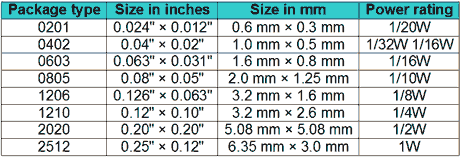
0402 means 0.4mm by 0.2 mm certainly smaller than 1mm !!

0201 means 0.2mm by 0.1mm... I have not seen smaller yet..

both of these are smaller than the "pico" size of 1mm by .5mm ... so that must be with the additional bulk of the wires, or more likely soldered to a small chip of circuit board.

I'm in Z scale, so this stuff is needed when you want to light up an F7 number board ha ha!


Greg


I finally ordered some Hokie71!

I should have paid better attention to Casey's post. The tip of a sharp pencil should be the reference. I think the post of someone else (a troll) threw me off.

The lights arrived and they are so tiny! I think they are for much smaller scales. I do like the warm white light though. They're set up for 12 volts so they'd be brighter than my sample. They are so tiny that it almost broke when I removed it from the package and the wire got stuck.

DSC_2246DSC_2247

Attachments

Images (2)
  • DSC_2246
  • DSC_2247
Greg Elmassian posted:

0402 means 0.4mm by 0.2 mm certainly smaller than 1mm !!

0201 means 0.2mm by 0.1mm... I have not seen smaller yet..

If you use them, you really should learn exactly what the sizes really mean.  A 0.4mm x 0.2mm LED would be smaller than anything that I've ever heard of.  The 0201 is larger than your claim for the 0402.  You're confusing inches with millimeters.

The smallest Digikey has on their site is the 0201 footprint Kingbright APG0603SEC-TT, it's 0.65mm L x 0.35mm W x .25mm H.

A 0.2mm x 0.1mm LED, which is what you claim the 0201 footprint is, doesn't exist as near as  can see.  In any case, it would be virtually impossible to solder, even to a PCB using automated equipment.

I've used the "Pico" LED's from Evan Design and I've used the 0402 LED's from Ebay (check out my Corgi E-One Pumper With Custom LED Lighting Post) and I prefer the Evan Design LED's.   I'm sure it depends which supplier you order from but I had more than a few of the Ebay 0402's "burn out".   These LED's are very small and I would rather purchase a better product the first time than have to remove/replace ones that have been installed.   My 2 Cents.  YMMV.

Chief Bob (Retired)  

PUFFRBELLY posted:

I've used the "Pico" LED's from Evan Design and I've used the 0402 LED's from Ebay (check out my Corgi E-One Pumper With Custom LED Lighting Post) and I prefer the Evan Design LED's.   I'm sure it depends which supplier you order from but I had more than a few of the Ebay 0402's "burn out".   These LED's are very small and I would rather purchase a better product the first time than have to remove/replace ones that have been installed.   My 2 Cents.  YMMV.

Chief Bob (Retired)  

I do like the look of that truck!

I made the mistake of laying out a couple of 0201 resistors on a design once.  I went to solder the prototype, not realizing just how small they are!  I wrecked one board and finally got two more boards soldered.  I then made a self-imposed limit of 0603 parts for anything that I'll be hand soldering.  If I'm going right to machine assembly, I'll consider something smaller, but so far I haven't needed anything smaller.

Engineer-Joe posted:
PUFFRBELLY posted:

.... but I had more than a few of the Ebay 0402's "burn out".

Chief Bob (Retired)  

Well this is a good tip!

If I'm correct, there's only a 150 ohm resistor on them. I believe that is too small???

How many volts were/are you using?

The E-One Pumper is set up for 9 volts DC.  I did an Amtrak Police cruiser and an Ohio State Highway Patrol cruiser and both of those are set up for 6 volts DC.  I will have all LED vehicle projects set up for 9 volts DC going forward. 

Chief Bob (Retired)

So I believe these draw 5ma?

gunrunnerjohn posted:

The smallest Digikey has on their site is the 0201 footprint Kingbright APG0603SEC-TT, it's 0.65mm L x 0.35mm W x .25mm H.

A 0.2mm x 0.1mm LED, which is what you claim the 0201 footprint is, doesn't exist as near as  can see.  In any case, it would be virtually impossible to solder, even to a PCB using automated equipment.

I see this chart says either 1/32 or 1/16w?

If they draw 5ma and G posted a limit of three MTH LEDs per circuit, function, channel, whatever?

I have to guess that the MTH LEDs draw 20ma X3 max =60ma / 5= 12 per channel max?? Maybe 10 for safety?

Those wattages are typically for resistor power dissipation, though I suppose they could be applied to any package that size.  I didn't check the specifications of the 0201 LED's, but as you point out, they'd probably be lower current than the standard 20ma LED types.

From a Digikey Search on 0201 LED, it appears they have either a 10ma or 5ma rating, which makes sense based on the package size and power dissipation.

Engineer-Joe posted:

The lights arrived and they are so tiny! I think they are for much smaller scales. I do like the warm white light though. They're set up for 12 volts so they'd be brighter than my sample. They are so tiny that it almost broke when I removed it from the package and the wire got stuck.

DSC_2246DSC_2247

here's the warm white 0402 John.

I just believe that the seller of the 0603 sent me cool white's.

Engineer-Joe posted:
...

If they draw 5ma and G posted a limit of three MTH LEDs per circuit, function, channel, whatever?

I have to guess that the MTH LEDs draw 20ma X3 max =60ma / 5= 12 per channel max?? Maybe 10 for safety?

Is this limit something that MTH sent out in some kind of service-bulletin?  I think it's important to establish the actual capabilities of the PS3 lighting circuits since that's apparently how you're going to be driving these micro-LEDs.

AFAIK the PS3 LED outputs are "programmed" within the soundset on an engine-by-engine basis.  That's how you get that EVO chasing pattern if you load an EVO soundset.  Thus, the soundset also controls the brightness on a per-output basis since, as you point out, you do not see resistors in the wiring of the PS3 LEDs.  I think there needs to be a parallel effort to understand the PS3 lighting output capabilities.  For example, one can reasonably speculate that the output driving the Headlight LED might be driven "harder" than another output which drives a relatively dimmer indicator like, say, a number board or whatever.

As I recall, for PS2 (6V bulbs) there were occasional discussions about co-opting unused lighting outputs.  There too, the "trick" was to find a soundset that had the programming to properly drive the unused (i.e., unused in the stock engine) wire.

A new search of G's posts suggest they may drive up to 4 LEDs?

I can't find the one I saw saying 3 anymore. It was in a discussion about connecting lights and he replied about both PS2 and PS3 board's and maybe PS32 board as well?

 I shouldn't pin this on G as this engine is not the norm and is a specific case. It has some type of custom light display made like a flat thin panel that appears to have micro LEDs mounted inside???

I would like to find out what the "default" capabilities of the LED outputs are, that's an interesting question.  I know that George (GGG) stated some time back that the outputs will drive multiple LED's, but I don't know if adding more than one would simply end up making them all dimmer, or they actually modulate the brightness based on the usage.  I don't think the current would be limited by the FET driving the LED, but rather the PWM output on/off ratio.  I guess popping a 'scope onto an LED output could be a useful exercise to see what is happening there.

For PS/2, you could parallel up to around 4 bulbs at 60ma each on an output.  I have found that a vast majority of sound files, even steam, have the ditch lights enabled (go figure).  OTOH, a lot of the other outputs are hit or miss as Stan says.

gunrunnerjohn posted:
 

...I guess popping a 'scope onto an LED output could be a useful exercise to see what is happening there.

Nothing is so easy as the job you imagine someone else doing. 

I'd think this is something you'd want that test-fixture you showed in the EVO chasing thread so that further limits the population of someone else !

It's hard to believe the modulation would change based on usage though that could be determined in seconds once the mythical someone else has the scope hooked up.  In other words, just add an LED in parallel and see what happens (does the duty-cycle change).


Engineer-Joe posted:

...

It has some type of custom light display made like a flat thin panel that appears to have micro LEDs mounted inside???

I realize you are talking about different lighting application, but it seems the matter at hand wrt number of LEDs is about the chasing LEDs for the EVO from your other thread.  I assume MTH hasn't announced a G-gauge EVO.  Have they announced or do they sell a O-gauge EVO using the PS3 board?  As for your existing O-gauge EVO what size LEDs do they use?  It seems to me you don't need to worry about the 0201/0402 sized LEDs for the chase LEDs since the G-gauge EVO ought to have more space.  I think you need to choose an LED size based on how you're going to mount it on some kid of strip.  That is, I can't imagine the wiring jungle and mess of individually running 40 pairs or wires to 40 discrete micro-sized surface mount LEDs hanging in mid-air?!  Seems to me you need to design some kind of mounting strip that can be replicated as there seems to be some symmetry - at least left-side/right-side, but perhaps also front-side/back-side. 

Separately, from some online videos are those EVO chase-lights actually green?  Or are you planning to use green lenses?  The voltage/current characteristics of green LEDs are different than white LEDs though possibly not different enough to matter...just another nit to pick on.

I really did not care originally about what color they were. I always like it to look like the real thing though. There is something about the cool white LED that I dispise? If I wanted light blue I'd order light blue!!

 I prefer warm white in tone. Green would look good too I guess?

 I am building a G scale Evo and originally thought it would be cool to add lights. 40 pairs of wire sounds like a lot in my old ways. However, the pre-wired 0402s that I bought have tiny wires. I would divide the negative into the two purple returns on the boards. The positives would all get divided into the four channels that flash. So 10 positive wires on each. I don't even have wire anywhere near fine enough to match the LED's wires, yet. I ordered #26 and that might have been too big? Maybe #30??

 I had thought of mounting tiny LEDs to laminated plastic strips that could be glued to the frame. They would have the wires routed inside and maybe could be covered in some type of plastic gel?

 John, I know the PS boards pulse the power. I have had some experience driving components over my different careers. So I am reluctant to attach 10 regular LEDs to a circuit that may only drive 4. I did read your thought on they maybe just dim. I believe the circuit would not handle the extra load and I am not willing to try. So I am attempting at least, to create something that should work if my calculations are correct.


Last edited by Engineer-Joe
stan2004 posted:

Nothing is so easy as the job you imagine someone else doing. 

You gonna keep throwing that in my face?

stan2004 posted:

I'd think this is something you'd want that test-fixture you showed in the EVO chasing thread so that further limits the population of someone else !

It's hard to believe the modulation would change based on usage though that could be determined in seconds once the mythical someone else has the scope hooked up.  In other words, just add an LED in parallel and see what happens (does the duty-cycle change).

 I wait eagerly for that "someone else" to test this out.

Engineer-Joe posted:
 I had thought of mounting tiny LEDs to laminated plastic strips that could be glued to the frame. They would have the wires routed inside and maybe could be covered in some type of plastic gel?

Joe, I still like the idea of laying out a PCB to hold the LED's, it would make the wiring much simpler.  If needed, you could add buffering for driving the LED array.  I'd run the LED board down the side and make the wiring connection to the back of the PCB.  Here's a simple test I did some time back for an LED array, but this one only had three sets of LED's, but you get the idea.  For your application, I'd make the board skinnier and run the LED's in line, the board could be vary narrow.

I was just doodling one day thinking about a light chase board and started this.  The extra connections were because I was going to have five sets of three LED's, just never got around to playing with this again.  The connector holes on the right could be just pads on the back side to solder the connection leads to.  You could even incorporate balancing resistors if needed.

As far as the circuit power, like I said, you could easily run the LED's on a fraction of the power that stuff like headlights run on, so I doubt buffering would be needed.  Also, there aren't 40 pairs of wires when you put them all on a PCB, for twenty LED's in groups of four you'd have six wires, five switched and one common.

Attachments

Images (2)
  • mceclip0
  • mceclip1

I haven't had much spare cash and stuff has come slowly. Making mistakes and ordering the wrong supplies has made it worse.

Luckily, I think this will work for the radiators! ( although I second guessed myself again, and ordered another size)

DSC_2275

Making a scratch build engine costs much more than buying one at the store. I wish MTH had released more modern G scale engines.

That would save me much effort!

Attachments

Images (1)
  • DSC_2275

The LED's are in series, but that's just supposed to represent an example of what you could do.  Wiring them in any configuration is as simple as a few mouse clicks.  I just posted that as an example of something I was toying with some time back for a chase light bar.  Making a long and skinny PCB is not difficult, and for a PCB that is .25" wide and a foot long, you can have three of them for $15 from OSH Park.  I don't know how long your run would be, or if it would be broken up into several lengths, again I'm just trying to give you and idea how to scale it.  I think wiring 40 discrete LED's would be a giant PITA, and I'd sure much rather have them all on a PCB that I could just mount after figuring out how to enclose it in your green plastic filter.

Add Reply

Post
The DCS Forum is sponsored by
×
×
×
×
Link copied to your clipboard.
×
×