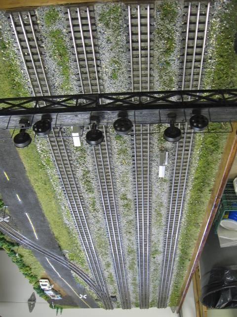
I found your request interesting, so I researched it. I found what I expected.
Each railroad hires engineering services to design the structures.
Each railroad determines their specifications based on their needs.
Each State has design requirements when you get near highways or for grade crossings.
The signals and their specifications seem to standardized. The support structures have basic engineering standards that must be followed for structural integrity, but each installation seems (or needs) to be designed for that location.
You may have to borrow from BNSF or search for the railroad that you are modeling. There are multiple patents for walk-out cantilever trusses that you can access, but the vertical support seems to be unique for the application.
The height would be determined by the clearance needed for trains and the distance from which the signal would be visible. I can only find old plans. AAR.org has publications, but members only access.
Perhaps a phone call to the railroad or a railroad engineering firm would provide some general specifications.
Just guess, SD70 height to top of cab 15'-7.5" + 6" of rail compared to height in photo. Have a photo of it under the signal? That one looks like it is at least 30' to the bottom of the walk-out truss.
Have fun! I learned a lot. Thanks.


