A while back we had a discussion about taking one of the cheap Chinese modules and wrapping the required components to power directly from track power, so here's my first mock-up.  The DC-DC module selected claims up to 3A, though I'd be perfectly happy getting maybe up to an amp, no way we're getting three amps, they get too toasty doing that.

You can see the bulk capacitance takes up some space, those are two 560uf 35V capacitors.  I opted for half-wave rectification because that way I can have a common DC ground with the input AC.  If I use a full-wave bridge, the complete output circuit needs to be totally isolated, that doesn't work in every case.

Here's the 3D view.

AC-DC Power Module Board 3D

Here's the board dimensions, it's .9" x 1.45".  The AC connections are on the left.

AC-DC Power Module Board

Here's the Chinese power module selected.  Note that the inputs and outputs have two connections each.  I use the outside four corners to connect the DC-DC board to the bottom bottom board, and the inner two outputs can be used to connect the load.

AC-DC Power Module Board DC Supply

Let me know what you think.  One other idea I had was to sandwich the DC-DC power supply below the main board and reduce the footprint.  I could leave a small hole in the upper PCB to access the voltage setting pot.  This might be another way to go.

Attachments

Images (3)
  • AC-DC Power Module Board 3D
  • AC-DC Power Module Board DC Supply
  • AC-DC Power Module Board
Original Post

Replies sorted oldest to newest

From painful experience, please be sure to do the math around the half-wave rectifier. Peak/RMS input currents will probably be higher than you expect, but my bigger concern would be the ripple current rating of those tiny capacitors. Perhaps you have already done this.

I might also provide instructions to transpose the input polarity of multiple units on the same circuit to cancel the DC component in the transformer as much as possible. I have never done any tests to see how much DC a typical train transformer will tolerate, but there is definitely a limit.

Perhaps a picofuse or "fuse resistor" on the input?

gunrunnerjohn posted:
... If I use a full-wave bridge, the complete output circuit needs to be totally isolated, that doesn't work in every case.

No question this is a thorny issue.  I don't think there's a simple answer.

My opinion is to go with the bridge...like the eBay LM2596 module.  For rolling stock applications I think there's enough precedence with MTH in particular that guys get the concept that the chassis is NOT "ground".  For track-side insulated rail triggering from outer-rail-common, I think a large % of applications can simply power the entire AC-to-DC module if that makes sense.

Separately, it's hard to tell but from the 3-D mockup I'm think that DCS inductor looks a tad small if the output current is in the 1+ Amp range?  I think a lot of applications will set the output to 12V DC so the input current will be 1A (or so).

Don't get me wrong, this will be a contribution to the hobby.  But I suffer from creeping feature disease and after years of trolling the OGR Electrical forum, some recurring themes might be:

- some kind of insulated-rail trigger mechanism...possibly with an opto-isolator to get around the grounding issue if you go with a bridge.  Specifically there are many accessories which could benefit from DC.  But some portion of the accessory is always powered, and some other portion must be triggered by, for example, an insulated rail.

- support for driving a relay.  This may be the only thing the module does.  The existing insulated-rail triggering modules with relays start at $10 and many don't have capacitor delays to de-chatter noisy wheels and dirty track.

- in lieu of a relay, support for driving 2 DC outputs selected by an input signal such as from an insulated-rail section.  This obvious application is the red/green outputs for a signal head.  The idea is one output gets DC power normally (e.g., the green LED or lamp), the other output gets DC power when the input trigger is active (e.g., the red LED or lamp).  This may mean adding a transistor or two.  This may mean adding 1K resistors assuming the DC module is set to 12V as 1K seems common for driving LEDs from 12V DC.

- they don't speak up, but IMO there's a silent majority of guys who simply don't want to power up the soldering iron!  To that end, I think screw-terminals on the inputs and outputs would be nice.  Obviously you can't just leave holes on the board to accomodate screw-terminals since that would then require soldering to put them on! 

I think it worth the time to identify specific applications in rolling stock or track-side accessories that would use this and make sure the module applies with NO SOLDERING!  Hard to say right now what you could sell these for but I think guys who routinely solder small components and such are NOT the target market.

I was waffling on the diode or bridge for the reasons stated.  I think you're probably right though, a bridge is most likely the safer choice.  I guess I need to assemble a "feature list" to try to come up with all the ideas and then see how to fit them into a module.  I knew the screw terminals would come up, it would be nice to find a reasonably inexpensive source for them.  I suspect that the sandwich idea is also going to be needed, I don't want the module to get too big.


It may be that the track-side application is a red-herring and the real need is for rolling stock.  The ~$3 eBay LM2596 AC-DC converter is bulky but no matter if being placed under the layout?  And there are versions of the AC-DC switching module that have screw-terminal inputs and outputs for ~$4 free shipping (eBay 391078368935).

Untitled

So drilling down the rolling-stock option without screw-terminal, I suppose it's similar to the Hennings LED module variants with flying leads or DIY soldering.  I see one AC-DC switcher offered with flying leads in an ice-cube form factor for ~$5 (eBay 251898304004).  It appears to come in fixed outputs of 5V or 12V DC which addresses a good chunk of applications.  So butt-splices or wire-nuts or whatever would be the interconnect method and no soldering.

ac dc switcher

Then of course the molex style connectors which adds cost but undoubtedly less space than the screw-terminals.  This one is only DC-DC but less than $2 and includes the "power cords" (eBay 161640651312 ).

lm2596 dc dc with power cords

In the absence of what you're proposing, I suspect most guys DIY the DCS-inductor, rectifier (bridge or single), and capacitor and mate it to a suitable DC-DC eBay module.  This has a bit more flexibility on cramming it in to rolling stock.  Here's a recycled photo of one I did.  Yes, tedious tight-quarters soldering but compact.

buck-boostassembly

So no answers and perhaps just feeding the analysis-paralysis beast.

BTW, that module appears to be the MP1584EN chip which is rated for 28V DC max.  Seems a few months back one of the guys was using one of these small DC-DC modules (not sure if it had the MP1584) and it popped so he went back to using one based on the LM2596.


Attachments

Images (4)
  • Untitled
  • ac dc switcher
  • lm2596 dc dc with power cords
  • buck-boostassembly

You're talking me out of it Stan.   You really can't compete with the Chinese on stuff like this, that seems clear.

I do believe the person using the 28V max input module that toasted it was feeding it 22 or 24 volts from an MTH transformer.  With 18V AC, you shouldn't hit 28 volts DC, more like 25.5V peak at the cap, and then there's a couple of diode drops through the bridge diodes...

I think I'll go back to stuff the Chinese haven't blanketed so thoroughly.

I like all these suggestions. From the standpoint of providing 4.5 vdc using the 16-17 vac lighting source (for incandescent and new Lionel LED lighting tracksides, I needed ac to dc with high efficiency. I already had some ac to dc linear supplies with readouts and dc to dc switching supplies with readouts. I decided to use the linear supplies for rectification, filtering, and drop a couple dc volts to their output and then feed the dc to dc switching supplies. This works well up to at least an amp and the readouts make it easy to set the voltages. The linear supplies are warm, but the switchers don't even get warm. Having it all on one board would be better. One decision maker was to regulate and filter the ac to dc rectification down from the peak so the switcher could have a cooler time of it.

In regard to ripple if using just a rectifier bridge or single diode, the easy calculation is V = (i x t)/c where i and t are in ma and ms. c is in uF which results in V being volts of ripple peak to peak. t is 8 ms for full wave and 17 ms for half wave. You can do this in your head when selecting a capacitor for filtering.

I'm ending up with boxes of various modules from China...changing my mind every time a more appealing choice comes along.

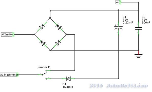
Just to throw it out there, you could use a simple jumper to make the board switch between full and half wave rectification.  I forgot about the choke for DCS, but other than that I think this works...

The capacitors are random values, you know what you actually need.  Anyway for less than a quarter in parts over that of using a full bridge you can add the option to switch between either option by moving a jumper.  

JGL

Looking at the prices of Chinese modules, I don't see where this can be made where it's attractive without losing money on every shipment.

Chuck, the one issue with calculating the input cap is knowing the ripple specification for the Chinese module.  I guess I'd have to dig into the chip datasheet to see what it tolerates.

Last edited by gunrunnerjohn

I solved all of my low voltage problems by use of a PC power supply. I bought mien at Radio Shack but I'm sure you can find them at multiple outlets. It provides a 5VDC, 12VDC, 9VDC output from a standard 120 AC input and I only paid about twenty-five bucks for it.

Of course you have to get a little creative bringing your voltages out to a terminal strips, but it came with a chart that showed the pin out on the connector. Return is the same for all voltages. Even without that a volt meter will ID your wires with little trouble. The trick is to ID the return and then you read from that to the other wires. The 5VDC wire, as well as each of the other voltages could run to a terminal strip with all off one side jumpier together.  Again, on my unit all the voltages return to the same wire.

The beauty of the thing is it also has a crow bar circuit to protect against shorts, unlike the wall warts that require to be open up should the internal fuse blow.

The unit that I  have even has a cooling fan on it.

Like I said it's a little tricky to work with but nothing a toy train person who works with DCS or Legacy can't handle.

Last edited by gg1man
gunrunnerjohn posted:

...  I guess I need to assemble a "feature list" to try to come up with all the ideas and then see how to fit them into a module. 

Yes, I think a one-size-fits-all AC-to-DC converter might be one of those "Jack of all trades, master of none."

On the layout track-side application, the 2 AC-to-DC applications that come up most often are:

Case 1. Insulated rail triggering of a DC relay or DC circuit for red-green signaling.

Case 2. Using AC accessory voltage to drive lighting such as 4.5V DC for Lemax, Miller, and Menards.

In both cases, the use of an external DC power supply whether it be a DC wall-wart, a PC power supply, or even a spare HO DC power pack seems to be a stumbling block.  In other words there seems to be great value assigned to deriving the "new" DC voltage from an AC source already on the layout (track AC or accessory AC).  From what I can tell it can be inconvenient to scrounge up a spare AC outlet and/or running the extra wiring.  So be it.

For case 1, there are off-the-shelf alternatives as I show in this posting.

https://ogrforum.com/t...74#40004359986239674

They are $10 and up.  The above post has your DIY schematic but I think putting it all together is not in everyone's comfort zone.  The off-the-shelf alternatives all "suffer" from limitations of one sort or another...such as not have the DCS inductor if powered from DCS command voltage, or lacking sufficient capacitance to demote flickering from dirty wheels/track.  So there is room here for a better mousetrap.  IMO what would bring something new to the party would be a non-relay version of the Lionel 153E that perhaps uses transistors to switch DC to the 2 outputs (red/green) which would allow a smaller form-factor.

For case 2, the Chinese alternatives on eBay ($3-4) make it nonsensical to even try!  The only missing piece would be a way to mate the DC-DC converters that have the digital LED voltmeter display to the AC track voltage or AC accessory voltage...without having to solder.  In other words how much value-added (i.e., how much can you charge) to attach a bridge rectifier?!

So again, I think the more interesting problem is in rolling stock.  The largest application there has been for bulb-to-LED conversion which of course requires AC-to-DC conversion.  Frankly the Hennings module goes a long way in that regard.  So what's left to be done?  I don't have the answer but I think it lies somewhere between Hennings AC-to-DC module and what you get in an ERR command-control module.  In other words, operating rolling-stock that needs more than the ~50mA of current from a Hennings module but not limited to TMCC command control like an ERR module.  Yes, this may be cutting it so fine that there's nothing left to grab on to but that's all I've got for now!

Last edited by stan2004

Actually now...my somewhat solution of using what I had in stock seems more and more to be the solution. An AC to DC linear regulator and setting a few volts drop to a DC to DC switching supply set to 4.5 vdc output.

But the suggestion above of this module for 3 bucks plus seems to solve all the requirements in one module...

Last edited by OGR CEO-PUBLISHER

Yep Chuck, there goes another one.   You do have to add the choke for DCS compatibility, but that's not sufficient to go to the trouble of making one.  I ordered three of these to have on hand, they look useful.

Stan, the 153E looks interesting, I've never even seen one of those.  Truthfully, if I were to do a signal module, I think I'd probably stick an 8-pin PIC on there and have maybe four transistor outputs and two inputs.  Make it do a bit more.  Perhaps one of the inputs would be a simple config that would step it through the various functions that were programmed into the module so it would be useful for signal, crossing gates, etc.  It could also do Red/Green or Red/Yellow/Green signals, and have several pre-programmed delay times.

Does anybody know the true commercial market for all these modules? Who uses them in what products? Hard to believe they are manufactured for the hobbyists!

As an editorial comment, the vast majority of people on this forum are hobbyists, and a lot of us are "old guys with a lot of stuff." There seems to be a bias toward spending $5 to use something I already have rather than spending $2 to buy the correct part for the job. Some of my other hobby interests have the same problem.

To expand/expound on Stan's comments, I think a lot of value could be added to some products simply by providing flying leads. Think of all the photos you have seen on the forum of $.50 bridge rectifiers and $.03 diodes mounted on $3.00 terminal blocks as a way to avoid soldering. Take some of the Chinese modules, put long #18 leads on them to work with wire nuts and you might have a winner.

Last edited by PLCProf
PLCProf posted:

Does anybody know the true commercial market for all these modules? Who uses them in what products? Hard to believe they are manufactured for the hobbyists!


I'm going to guess it is a hobbyist of a different sort.  It has proven difficult to find accurate and/or up to date numbers, but the best I can find shows over 3 million Raspberry Pi's sold as of March 2014.  Arduinos are even harder to track because there are many more clones out there.  The figures I can find suggest over 1.5 million boards just between genuine Arduino boards and SparkFun branded boards are sold each year.  Other articles and community responses say for every genuine board made at least 2 clones are made.  All told you're looking at something in the neighborhood of 5 million+ micro-controller boards sold in a year, of just the two most well known types. Never mind the odd balls like Edison or the BASICStamp.  

I'm sure some of the modules are designs salvaged from other applications, especially things like power supply modules, but the majority are simply catering to the explosion of people that find tinkering fun.  Things like MakerFaire and the Make! movement in general also help to promote learning and making this "high tech" accessible to all.  


On the later points, chances are you can sell a lot of units of $3 module with pigtails on it for $15+.  I've seen endless examples of folks here on the forum choosing to spend 5 to 10 times more money to keep from having to put together a few wires.  Most recently I recall some LEDs being sold for $3 a piece for less than 25 cents worth of parts.  (Mind you, not regulated, just a resistor, cap, and what is claimed to be a bridge rectifier) There is a huge market for plug and play devices in the train hobby.  It seems folks would rather spend money than do work, and that is a good arrangement for folks that know how to do the work.  

JGL

gunrunnerjohn posted:

Stan, the 153E looks interesting, I've never even seen one of those.  Truthfully, if I were to do a signal module, I think I'd probably stick an 8-pin PIC on there and have maybe four transistor outputs and two inputs.  Make it do a bit more.  Perhaps one of the inputs would be a simple config that would step it through the various functions that were programmed into the module so it would be useful for signal, crossing gates, etc.  It could also do Red/Green or Red/Yellow/Green signals, and have several pre-programmed delay times.

Everyone has their opinion on the value of pre-wiring, packaging, branding ("Lionel" printed on it), and so on.  I think you could indeed add some value with a 25 cent microcontroller to add logic and timing to Case 1.   While I can't imagine anyone doing this, you may recall I showed how you can take a Hennings AC-to-DC LED module plus a $1 eBay 12V DC relay module to essentially duplicate the functionality of a 153E.  It additionally has the DCS inductor.

153e functionality plus dcs inductor

The post which includes and video proof-of-concept is here:

https://ogrforum.com/t...75#40004359636588575

This is not pre-wired so it really isn't a solution...but it may be the only modular alternative available today to duplicate 153E functionality with DCS compatibility and de-chatter! It does require wiring/assembly/soldering but don't need to muck around with individual components.


Attachments

Images (1)
  • 153e functionality plus dcs inductor

Don't forget "tools".  While the DIY electrical guys have a soldering iron (or 2 or 3), I'm not sure everyone in the hobby has one.  Then there are those insanely (high) priced crimping tools to make connector inserts for some of the wiring used in the hobby.  And the tool I have the most "fun" with is the digital multi-meter which I find a lot of guys do not have and hence my delight in pointing out the "Free with Coupon" meter you can get at Harbor Freight...perfectly adequate for a wide variety of DIY electrical projects around the layout!

ogr hf meter measuring ps1 smoke motor - Copy

But to keep on-topic, wrt the digital multimeter, that the 4804 AC-to-DC converter module from Miller is pre-wired and pre-set to 4.5V DC (no meter required) makes it a solution to the Case 2 application for AC-to-DC conversion for building lighting.  $12.95 MSRP.

MIL-4804-2

From what I can find on eBay, you can't get an AC-to-DC switching converter WITH on-board meter if you don't have a DMM to set the module to 4.5V DC.  I see some for the AC-to-DC linear (LM317) converter modules WITH on-board meter but I think there's consensus that if stepping down from accessory 14-16V AC to 4.5V DC you do not want to use a linear converter.  So two modular-level low-cost DIY alternatives are

1) separate bridge-rectifier/capacitor module followed by a DC-to-DC converter with on-board LED DC voltmeter. 

ac-to-dc option 1

2) AC-to-DC converter with a separate LED DC voltmeter monitor module.

ac-to-dc option 2

I know I'm not telling you guys anything new but this might be a good repository of options that can be referred to since the "how do I" questions seem to pop up with some regularity...


Attachments

Images (4)
  • MIL-4804-2
  • ac-to-dc option 1
  • ac-to-dc option 2
  • ogr hf meter measuring ps1 smoke motor - Copy
Last edited by stan2004
PLCProf posted:

What we need is a module that puts 8 of these in a row, plus de-chatter, for $8. I posted this a few years back but the thread disappeared or my eyes went dim.

I'd let you remove the 120VAC coil connection. Add a DCS inductor and it would be a winner.

http://controlconsultantsinc.c...-1030vacdc-2381.html

We wait with eager anticipation for your product announcement.   I know I won't be building it, I can't afford to ship a $20 bill with each unit!

I suggest starting a different thread specific to a new/proposed "signaling" product whether it be an 8-channel relay system or $20 bills folded origami-style to look like relays.    No rules against topic-meander, but this thread started with a proposal to convert low-voltage AC-to-DC...and the trials and tribulations therein.  

Just my 2 cents.  No refunds.


PLCProf posted:

What we need is a module that puts 8 of these in a row, plus de-chatter, for $8. I posted this a few years back but the thread disappeared or my eyes went dim.

I'd let you remove the 120VAC coil connection. Add a DCS inductor and it would be a winner.

http://controlconsultantsinc.c...-1030vacdc-2381.html

 I use these at work all the time , they are bullet proof. I also use them quite extensively on isolated rail applications.

I still add a couple diodes and anywhere from a 480uf to 1000uf cap to keep the relay from chattering.  A 1000uf cap

give me about a 2 second post delay on the relay, Great for crossing gates.  The number we use is the MR101. ( they also include

a nice mounting bracket ) That will handle 8-230V input.

Bruce..


stan2004 posted:

I suggest starting a different thread specific to a new/proposed "signaling" product whether it be an 8-channel relay system or $20 bills folded origami-style to look like relays.    No rules against topic-meander, but this thread started with a proposal to convert low-voltage AC-to-DC...and the trials and tribulations therein.  

Just my 2 cents.  No refunds.


Probably prudent, I'll mull over the possibilities.

I have an early TMCC Lionel PA-1 that I am upgrading with a simple 555 chip fade/flash circuit to simulate a Mars light (video).  The circuit runs off a 9v battery.  I would like to power it off the incandescent headlight supply. Powered in conventional, this measures at track voltage minus 1 VAC (I run command).  Can I insert an inductor/ bridge/cap/ circuit feeding this DC-DC regulator into that headlight circuit? I would leave the original bulb in parallel for the "constant on" headlight.

image

If there is a problem inserting it into the headlight circuit, I'll run it from track power, but the Mars light will be on all the time.

Bob

Attachments

Images (1)
  • image
Videos (1)
trim.D0412A6C-7530-423F-ABB6-B1D2041471D3
Last edited by RRDOC

You can do it with three components and forget about the eBay module, you don't need much current for an LED circuit on a 555.  You need most of these components to use the eBay module anyway, you're just adding the little TO-92 regulator.

If you want the DCS choke, it's four components.  The choke, a 1N4003 diode, a 220uf 35V capacitor, and an LM78Lxx regulator.  The xx is the voltage you'd like, probably 05 or 06 for this application.

DC from Headlight Voltage

Attachments

Images (1)
  • DC from Headlight Voltage

If you're only drawing 20ma or so from the supply, there will be no ripple, the 555 will work fine.

Yep, the switchers are for higher currents.  I presume you did see my posting on several designs using the switchers?

AC-DC Power Module for Model Train Applications

Or this one with a linear regulator?

"Universal" AC-DC Power Supply for O-gauge Locomotives and Rolling Stock

Last edited by gunrunnerjohn

Yes, I have been following them.   Learning a lot from the discussions.

Your Programmable Chuff Generator arrived in the mail last week.  So when I finish the Mars Light in the PA-1, I'll be tearing apart my K-Line Scale K4 to install it and the Super-Chuffer.  

Do I get some kind of  honorary Electronics Technician diploma when I finish it? 

Bob

gunrunnerjohn posted:

You can do it with three components and forget about the eBay module, you don't need much current for an LED circuit on a 555.  You need most of these components to use the eBay module anyway, you're just adding the little TO-92 regulator.

If you want the DCS choke, it's four components.  The choke, a 1N4003 diode, a 220uf 35V capacitor, and an LM78Lxx regulator.  The xx is the voltage you'd like, probably 05 or 06 for this application.

DC from Headlight Voltage

John

I have some 25v 220uf caps around.  Can I use them?

Check my math:

20v AC RMS X 1.4 = 28 V peak to peak.  But divide by 2 since the cap only sees half wave output = 14 V peak.

Bob

It's 20V AC RMS x 2.8 = 56V pk-pk.  Divide by 2 since cap only sees one polarity after the diode = 28V peak.  Of course the diode introduces a drop of just under 1V but that's still more than 25V so I'd go with 35V capacitors.

The 78Lxx family includes the 78L09 (9V output) if you're trying to replace the 9V battery.  In this family of parts, the pin GRJ shows as "ADJ" is "GND".

Untitled

Attachments

Images (1)
  • Untitled

Thanks Stan.

Better to ask than to fry components!

I got these instead of the TO-92:

LM7809 L7809 Positive Voltage Regulator TO220 9V 1.5A

Bigger and beefier than I needed, but they were still cheap from a US seller and I did not have time to wait for the TO-92s shipped by the slow boat from China.  Thanks for the tip RE: pinouts.  I may get some later.

Bob

RRDOC posted:
... So the niche for the ebay DC-DC regulators is higher current applications?
There is an asterisk on this question since you chose the "beefier" TO-220 package instead of the TO-92 package.  The larger package can safely dissipate more power.  Let's be specific.  So in your case you are starting with, say, 25V DC going into the regulator and 9V DC coming out of the regulator.  Because it's a so-called linear regulator (as opposed to a eBay DC-DC switching regulator) the current going in equals the current going out.  If your 555 circuit plus LED draws, say, 20 mA as suggested, the power going into the regulator = V x I = 25V x 20mA = 500 mW.  The power going out (into the circuit) is 9V x 20 mA = 180 mW.  So the package must dissipate 320mW or about 1/3rd of a Watt goes up as "wasted" heat.  1/3rd Watt will actually make a TO-92 package hot to the touch.  The TO-92 package can safely dissipate that much power but the larger TO-220 package can safely dissipate much more (several times more).  And in the trivia category, why is it called a TO-xxx package in the first place?  So waaay back a simple 3-legged transistor was the most sophisticated semiconductor you could buy.  Various packages were developed referred to as Transistor Outline (TO).  It obviously stuck since that same package designation is used for the LM7809 and zillions of other components...and the LM7809 probably has a dozen or so transistors inside it.
 
Now getting back to the switching part.  So in this relatively low current application you must supply 500 mW to get 180 mW of "useful" power for an efficiency of 36%.  An eBay DC-DC module operating at this low current level might have an efficiency of, say, 75%.  So you would only need to supply it with about 240 mW to get that same 180 mW of output.  That's half as much power to do the same thing!  And rather than 320 mW of wasted heat, you only have 60 mW of wasted heat.  What is really interesting about the switching converters is the current going into the module.  For the same 25V DC going in, you only need 240 mW of power which means only about 10 mA of current (instead of 20 mA).  This halving of the power & current is of minor consequence in this circuit, but become big wins in higher power/current applications...such as cooler operation, smaller gauge wiring, etc..


Stan

Thanks for the analysis.  I really appreciate you and GRJ taking the time to explain the nuances of circuit design so clearly.  

It's surprising how energy inefficient the circuit is with 64% of the power going to heat.  Fortunately it's just a drop in the bucket compared to the draw of the locomotive it will be installed in.

Bob

Add Reply

Post

OGR Publishing, Inc., 1310 Eastside Centre Ct, Ste 6, Mountain Home, AR 72653
800-980-OGRR (6477)
www.ogaugerr.com

×
×
×
×
Link copied to your clipboard.
×
×