I want to put one of Gunrunner John's TMCC battery eliminator in my older Sunset Models/3rd Rail Northern, but the tender does not have a pickup roller.  So I want to tap into the 18v feed from the locomotive.  The problem is I can't tell which wire in the bundle from the locomotive is the power to hook the wire to; there are 1 blue wire, 2 brown wires, and 5 black wires.  It is a TSA  board with a OEM NOR B LIONEL TRAINS chip.

Can someone identify which is the correct 18v wire to hook up to the battery eliminator?

Thank you!

Attachments

Images (2)
  • DSCN3488: TSA board
  • DSCN3489: Engine/tender tether
Original Post

Replies sorted oldest to newest


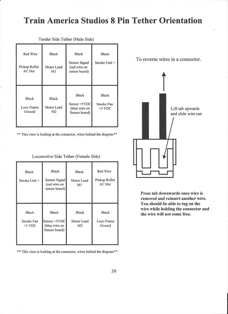
Top  Tender side Tether (Male side)

Red (Pickup roller AC hot), Black (Motor lead M1), Black (Sensor signal/red wire sensor board),  Black (Smoke unit +)

Black (Loco frame ground), Black (Motor lead M2), Black (+5VDC blue wire sensor board),  Black (Smoke Fan +5VDC)

**This view is looking at the connector wires behind the diagram**    


Bottom Locomotive Side Tether (Female Side)   

Black (Smoke unit +), Black Sensor Signal (Red wire, sensor board), Black(Motor lead M1),  Red  Pickup roller AC hot

Black(Smoke Fan +5VDC),  Black Sensor (+5VDC Blue wire, sensor board), Black(Motor lead M2), Black Loco Frame Gnd.

**This view is looking at the connector wires behind the diagram**    

Last edited by Mike CT
Mike CT posted:


Top  Tender side Tether (Male side)

Red (Pickup roller AC hot), Black (Motor lead M1), Black (Sensor signal/red wire sensor board),  Black (Smoke unit +)

Black (Loco frame ground), Black (Motor lead M2), Black (+5VDC blue wire sensor board),  Black (Smoke Fan +5VDC)

**This view is looking at the connector wires behind the diagram**    


Bottom Locomotive Side Tether (Female Side)   

Black (Smoke unit +), Black Sensor Signal (Red wire, sensor board), Black(Motor lead M1),  Red  Pickup roller AC hot

Black(Smoke Fan +5VDC),  Black Sensor (+5VDC Blue wire, sensor board), Black(Motor lead M2), Black Loco Frame Gnd.

**This view is looking at the connector wires behind the diagram**    

My tender side bundle is 1 blue wire, 2 brown wires, and 5 black wires .... it's for the OEM  NOR B Lionel Trains chip in the TSA board.

Which of these relate to the hot pickup roller AC?  If I use an ohm meter is there something else in the pickup roller circuit that could throw off the result, show a false connection?

?????   Don't know.  ?????    Appears from the diagram, looking at the Tender Side tether,  top Diagram, top row, left facing the end of the plug is the AC Hot from the Pick-up roller.  

With your ohm meter, you should be able to read continuity, Locomotive pickup roller, to the top right pin.  Top right pin, of the locomotive plug,  should match to the top left pin on the tender tether.   ?????

This a situation where you will have to figure it out on your own. The TAS board might actually have the what it is connected to labeled on the board. Test each wire with your volt meter on the omega symbol until you find less than 1 ohm going to the pickup roller. Then follow it back to the board, unplug and test again to make sure

Add Reply

Post
×
×
×
×
Link copied to your clipboard.
×
×