Please see attached right half of the track plan. Please correct me where appropriate and add anything I may have missed
Replies sorted oldest to newest
Are these Ross ready switches with the electrical bridges connecting the rail segments or simple manual switches with all of the rail segments electrically isolated?
If they do not have the electrical bridging, you do not need any insulating pins. Actually you have the opposite problem, and need to make sure that all legs are getting power from somewhere. That's what I do on my layout. Switches are a natural block separator.
Are you trying to do non-derailing? That's a whole different story.
When we buy Ross turnouts, we get the regular ones as opposed to Ross-Ready. The reason is we have control over which rails are live. Makes blocking much easier. On larger turnouts, using the regular ones allows tying closure rails on the non-thrown side to hot to compensate for engines with odd pickup roller spacing.
If you have Ross-ready, you can de-solder or cut the bridging bars if you have special insulation requirements.
Matt, those are my feelings exactly. I bought a lot of mine used, so I ended up with a mixed batch. Eventually I got smart and found the ones without the bridging and used them on the mainlines. I saved the ones with for yards where all three legs are in the same block.
I'm not exactly sure what he's trying to accomplish here. Need more information.
Please see attached right half of the track plan. Please correct me where appropriate and add anything I may have missed.
Best wishes,
![]() Mike CT
Mike CT![]()
All, thanks for the great input. I think I can figure it out now. Yes, these switches are Ross Ready. However, I'm also interested in non-de-railing as well. What are the pros and cons of doing this ? How does that change the isolation as previously discussed.
Mike
Mike,
You did not say if you were using DZ-1000 or DZ-2500 switch machines. Below are diagrams for each showing setup for non-derailing and where the insulating pin needs to be to isolate a spur track.
DZ-1000
DZ-2500
Attachments
Mike: you may want to note that we, Fort Pitt Highrailers, have done a lot of remodeling of our existing layout. Here are some pictures of cuts, done with a dremel tool and insulated with styrene strips glued in place with CA. A lot of this work was done for the non-derail feature added to the switches.
Also note that the non-derail feature is important if for some reason you need to do power routing through the switches. Sometimes when you place switches or other track detail close together, you can create electrical holes, where both contact pick-up rollers on an engine hit dead spots at the same time. Your back to back switches between U and T have a potential for this problem.
Pictures of isolation added on a remodel. Non-derail input track section near the switch frog wired to a DZ1000 switch motor.
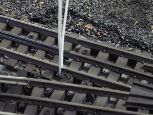
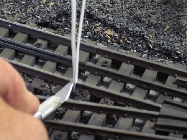
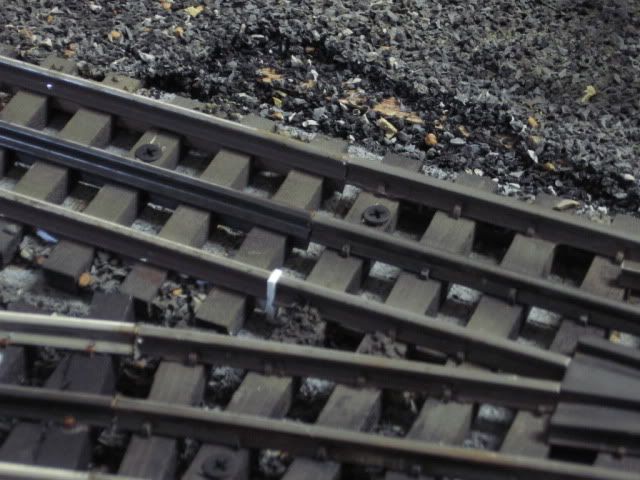
Glued in place with CA Cyano-acrylate, super glue.
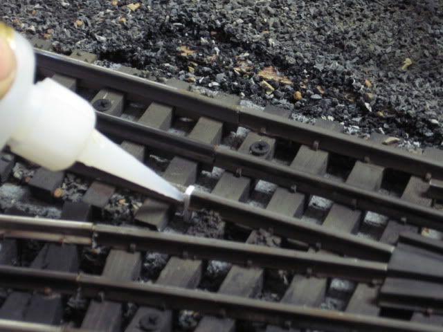
Both isolation sections ready for the wire to be solder.
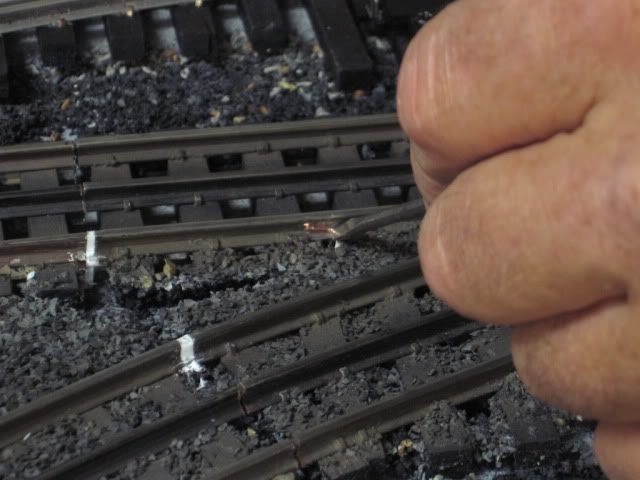
Mike CT posted:Mike: you may want to note that we, Fort Pitt Highrailers, have done a lot of remodeling of our existing layout. Here are some pictures of cuts, done with a dremel tool and insulated with styrene strips glued in place with CA. A lot of this work was done for the non-derail feature added to the switches.
Also note that the non-derail feature is important if for some reason you need to do power routing through the switches. Sometimes when you place switches or other track detail close together, you can create electrical holes, where both contact pick-up rollers on an engine hit dead spots at the same time. Your back to back switches between U and T have a potential for this problem.
Pictures of isolation added on a remodel. Non-derail input track section near the switch frog wired to a DZ1000 switch motor.
Glued in place with CA Cyano-acrylate, super glue.
Both isolation sections ready for the wire to be solder.
When I have cut rails, I have never put anything in the cut and it seems to work. Is the plastic just for extra protection just in case the rail moves?
thanks
tony
"When I have cut rails, I have never put anything in the cut and it seems to work. Is the plastic just for extra protection just in case the rail moves?"
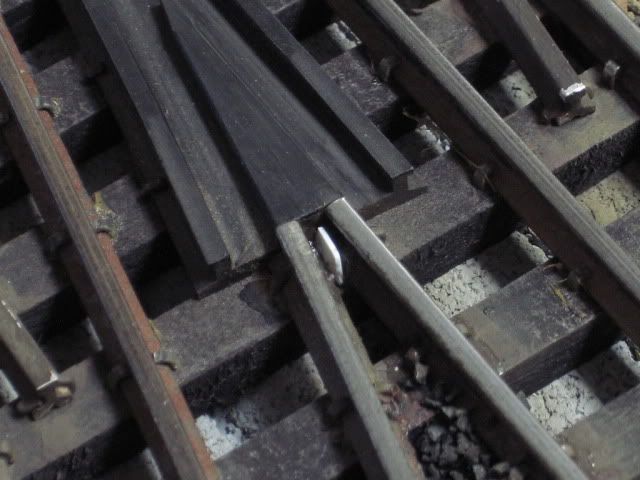
Yes, the styrene strips pictured, add stability. A very narrow cut the rails could touch. I believe Ross or Gargraves has plastic pins also. Also note that I had to add a piece of styrene at the frog, on this switch, the two isolate rail sections were touching.
doing some research on possible scenarios to wire up switches and found this thread from a year ago... the goal of the project is to reduce wiring since there will be nowhere good to hide it on a eye level shelf layout.
when wiring a dz1000 switch machine in a reverse loop is it possible (or recommended) to ONLY wire it for non-derail and use track power to actuate it? and not have a push button dz1002? the reason is there is one switch on my layout is over 30' from the control panel and if I don't have to run an additional wire out to it the better.
thanks!


