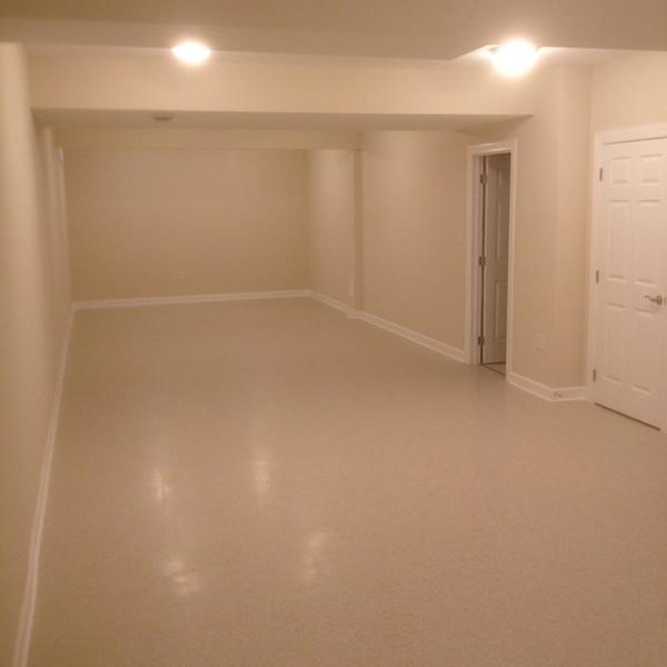
Today is the start of the design and construction of version 2 of the PRR Panhandle Division.
Here is the blank canvas.
The Prototype - Background & History
This layout is my second attempt to model the 7 miles of the PRR Panhandle that ran through the northern panhandle of West Virginia and Steubenville, OH. The Panhandle was a second mainline of the Pennsylvania Railroad that ran from Pittsburgh to St. Louis. It existed from 1848 through 1995. Grif Teller immortalized the double track bridge across the Ohio River in the painting “Crossroads of Commerce” which appeared in the 1953 Pennsylvania Railroad Calendar. That bridge still stands and the track using it serves Weirton Steel (now Arcelor Mittal) and the brick refractories and businesses on the New Cumberland secondary. Unfortunately from Weirton Junction through Burgettstown and points east, the track has been pulled up and the right of way has been converted to a hiking / bike trail.
I grew up in Weirton, WV in the 1950s & 1960s. I left in 1978, but still have family and other ties in the area. The PRR double-track bridge at MP 42.11 was always a source of fascination for me, even as a small child going to Steubenville with my parents and grandparents. However, it was not until I saw Teller’s painting (in the late 1990s) that I realized what I wanted to model.
Vital Statistics of the proposed Layout:
- Size & Shape: Folded dog bone – 11’ x 41’. In addition there is a 10' x 6' staging yard behind the eastern backdrop. Total dimensions are 11’ x 47’ (517 square feet).
- Track: Mostly GarGraves with some Curtis sectional curves, Curtis Hi-Rail turnouts, and Ross Custom Switch turnouts. Mainline curves are O72.
- Yards: Weirton Junction, Weirton Steel, Coal Mine Spur, Staging.
- Command System: TMCC. Turnouts have Z-Stuff DZ-2500C switch machines and are both TMCC and pushbutton controlled.
- Wiring & Blocking: 8 power districts will be supplied from 1 centrally located power distribution panel. Bus wiring will be used.
- Power: 6 Lionel 180 watt PowerHouses and 2 Lionel 135 watt Powerhouses will supply power to districts 1-8. Two (2) K-Line PowerChief 120 transformers will power switch machines, lights, and some AC accessories. All DC accessories, building lights, traffic signals and street lights get their power from various 3VDC, 5VDC, and 12VDC power supplies.
- Signals: Z-Stuff DZ-1060 PRR position signals (9) & MTH PRR signal bridges (2). The layout is only signaled for travel in the counter-clockwise direction.
Differences between Version 1.0 and Version 2.0
I feel that the increase in size (primarily length) will contribute to a more accurate representation of the area. Panhandle 1.0 was an ambitious design crippled by limited space. Panhandle 2.0 is similar in its major design aspects, but the additional space will allow those features to be separated by scenery. My intention is to avoid crowding layout elements and give a real sense of distance between the features.
Construction Goals:
- Select a uniform height (50”) that facilitates working underneath comfortably.
- Avoid grades and take steps to make track as issue-free as possible.
- Make the fascia, table tops, and legs as attractive as possible; use high quality wood and stain exposed components. Plan for layout skirting.
- Minimize the use of cookie cutter sub-roadbed.
- Make aisles wide enough for comfort and provide space for seating at least a dozen people.
Operational Goals:
- Allow the simultaneous operation of at least 3 trains on the mainline and up to 3 switchers in yards or spurs.
- Use a signaling system that prevents collisions.
- Have curves large enough to permit the use of the largest PRR locomotives and scale passenger cars (requires O72).
- Permit the running of long trains (10-20 hoppers or 8 passenger cars).
- Allow operating sessions to take place.
Electrical Goals
Panhandle 1.0 (2005-2016) was originally conceived (back in 1997) as a conventional layout (a tip of the hat to Rich Melvin for his help on conventional electrical blocking ![]() ). In 2005, I decided to install TMCC, but was influenced by the arrival of DCS. After trying a DCS/TMCC combination during construction, I decided TMCC was the direction to pursue. In 2007, the change was made to solely TMCC. Home run wiring and light bulbs (as block power indicators) were retained in the design.
). In 2005, I decided to install TMCC, but was influenced by the arrival of DCS. After trying a DCS/TMCC combination during construction, I decided TMCC was the direction to pursue. In 2007, the change was made to solely TMCC. Home run wiring and light bulbs (as block power indicators) were retained in the design.
For Panhandle 2, the electrical plan divides the layout into 8 blocks or power districts – 4 mainline, 1 separate loop, and 3 yards - with the ability to individually control power to the yards. The loop and mainline (districts 1-5) and yards (districts 6-8) are all command controlled. District 1, which is a separate loop for the kids (River Route), will be operable in either command or conventional mode.
- Eliminate multiple power distribution panels.
- Simplify and improve labeling for all wires.
- Make use of 2-color zip-cord where practical.
- Improve wiring reliability and crimping techniques.
Much more detail to follow, but those are my goals and thinking as I take the first steps down the road.
As always, your thoughts, suggestions, and questions are welcome.
George


