
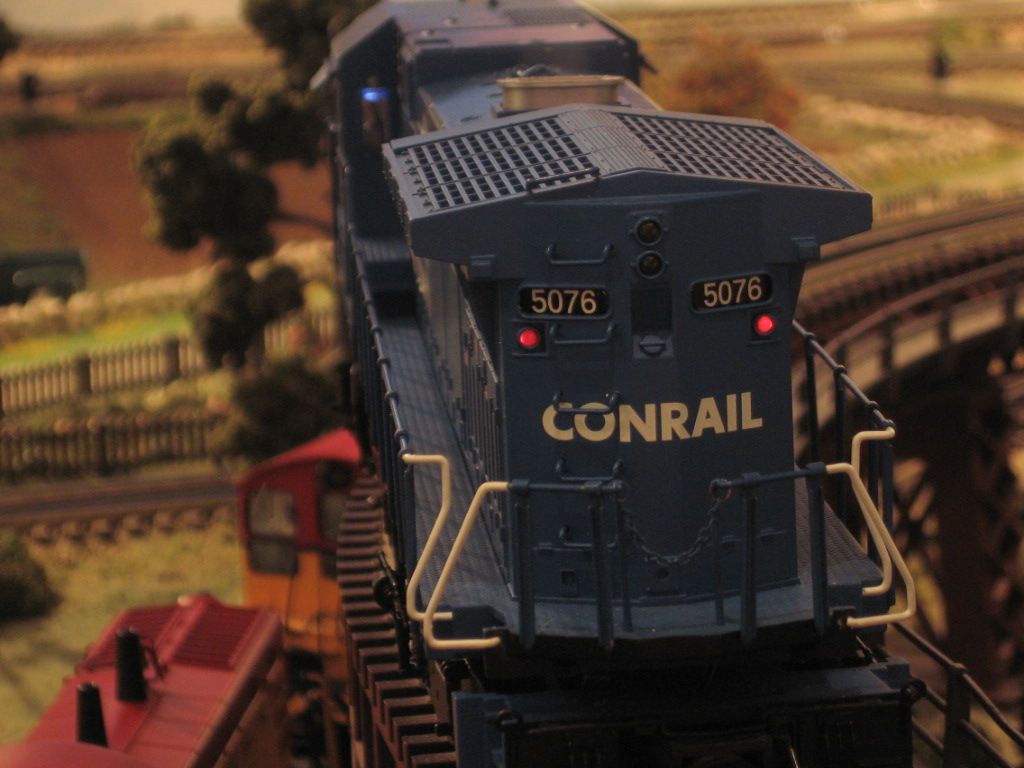
Has anyone ever added ditch lights to their PS2 locomotive?  I have 2 that are out of FRA compliance as of now and would like to bring them up to standard


Any tips or wiring diagrams would be really helpful! What bulbs did you use and what size resistor if any was needed?  How many spots does an MTH board have available for adding lighting effects?  If I could I would like to start going all out on my locos...ground lights, stepwell lights, ditch lights, rotating beacon.  What's possible?  I know that Surface Mount LEDs would be easiest but I have heard horror stories of LEDs and PS2 any tips? 


Thanks guys!

Original Post

Replies sorted oldest to newest

Dave thanks for the link! I was able to find the wiring diagram!


Joe what issues did you run into?  From looking at this wouldnt the board be able to run all of these different lights that go into the wiring harness?  If it would be easier I could just buy the ditch light wiring harnesses and plug them straight into the board correct? The diagram says to use the MARS light for the number board if you dont have a Mars light. I guess I could chain ground lights off of the number board wires? Or are you saying that the PS2 board cant handle that much current?

Attachments

Hi Will,


Each of the lighting circuits on the PS2 board will handle a maximum of four "grain or wheat" bulbs.  Most of the sound files have been programmed to follow the same wiring as in the pdf.  However, there have been a few exceptions over the years.  You will need to download a sound file for an engine that had ditch lights.  If the wrong lights flash when you download the sound file you will need to swap some wires.

I recently did a PS 2 upgrade to a GS 5 loco and the tender had 3 red marker lights. The tech at MTH advised not to simply add another red LED to the two already there saying that it could blow out the FET that controls that circuit. Instead he said to add another double set to the 8 pins connector which supports 2 marker light circuits as well for the Mars light. With help from GGG I was able to do this not wanting to test the theory of blowing out the FET. Hope this helps.

Regards,

Joe Geiser

The bulbs in question are LED's, you can have a lot more than two of them connected to a single output.  The PS2 outputs drive two 60ma 6V lamps, so by logical extension, if you have six LED's, you could still support them at 20ma each.  Also, you can increase the resistance and drive the LED's at 10ma with little loss in intensity and drive a dozen from one output.

Since I've measured the current draw of the supplied incandescent bulbs at 6V and they come out to 60ma, I have to assume that each circuit will handle at least 120ma.  Since Dave says four bulbs, I can't imagine you running into limitations with LED's, standard LED current is 20ma max.  Obviously, it's possible to fry one of the FETs, just short it and it's gone.   However, unless you had a large quantity of LEDs connected to one circuit, or you used incorrect resistor values and ran excessive current through them, I'm not sure how you cooked the output.


Originally Posted by Enginear-Joe:
Originally Posted by joe geiser:
Originally Posted by Enginear-Joe:
Wouldn't connecting four bulbs to the marker light circuit pop the FET?
Each of the outputs on the 8 pin connector is driven by a seperate FET, hooking 4 LED's to the same output (same FET) would overload it.
Regards,
Joe Geiser

John ,did you read this??


Yes, but did you read this?


Originally Posted by Dave Hikel:
Each of the lighting circuits on the PS2 board will handle a maximum of four "grain or wheat" bulbs.


In this case, I think I'm going to take Dave's word for it, I think he's pretty well versed on the PS/2 stuff.   The grain of wheat bulbs they're using are the 60ma ones I mentioned.

Originally Posted by Rod Stewart:

Dave Hikel;

If you are still following this thread, i thought I read somewhere that PS-2 lighting circuits were rated for up to 200 ma per circuit.

Can you confirm that?


Joe, you are missing a rail I think!


Rod

Rod, John,

     As I am new to PS 2 I usually defer to the experts and rarely give advice on subjects that I am not familiar with. In this case I was quoting the advice of a MTH tech who I spoke with regarding this subject.  He told me that a single marker outlet would support two lamps (LED) and simply adding one more would overload the FET on a PS 2 3 volt board.
     So, in the interest of offering the best advice to Will (author) as opposed to winning any arguement here, I would  simply say call the experts at MTH and don't risk a costly repair. Hope this helps

Regards,

Joe Geiser


PS After reading all the responses I think we are talking about two different circuits, Lighting which would drive the incandescent lamps and the auxillary lighting circuit )8 pin connector) which drives the LED's, I was referring to the aux.lighting output.

Last edited by joe geiser

 Wait, so there's a limit??? I thought I could hook up a frying pan????

Thank you for the explanation. I hope some listen to it. I bet some won't. When I heard that original answer on my old post, I tried to connect ground and step lights. They were LEDs. The result was not pretty.

 So you just can't hook them up anywhere. Some of these answers aren't complete enough to make valid decisions on. Maybe we should require a warranty from posters to back up they're statements????

The ultimate power source with any O-scale locomotive/engine is rail pick-up.  I had powered marker light LED's (pairs hooked in parallel) and ditch light LED's (pairs hooked in parallel) hooked in series with at the least a 470 ohm resistor and in some cases the resistance was more.   It depends on the LED's used and of course the track power voltage (Running Command at 18VAC).  Yes, I popped a few LED's before I got it right.  Best to check with the supplier of the LED's.   Some of the electronic's upgrades left Marker LED's out in left field.   I E-mailed Atlas when this older Dash 8 40 was upgraded to an EOB drive.  With some instructions from very good Atlas Technicians I was able to get this older Atlas engine running and lit like a Christmas tree.  

Originally Posted by joe geiser:
 

     So, in the interest of offering the best advice to Will (author) as opposed to winning any arguement here, I would  simply say call the experts at MTH and don't risk a costly repair. Hope this helps

Regards,

Joe Geiser


PS After reading all the responses I think we are talking about two different circuits, Lighting which would drive the incandescent lamps and the auxillary lighting circuit )8 pin connector) which drives the LED's, I was referring to the aux.lighting output.

Hi Joe;

Yes it's not about winning an argument in my view. It's about gaining a better understanding of the limitations of the board design.

My understanding was that all lighting circuits are powered by the same FET part, and could handle the same total circuit load, be it 120 ma, 200 ma, or whatever.

I was just hoping that someone with more detailed knowledge such as Dave, might be able to clarify the picture for all of us.


The best,

Rod

Joe, I'm curious, do all technical discussions qualify as "arguments" to you?


I'm also very interested in the answers to the question, but I don' think I'll "argue" about it.


Stan appears to be correct in this case, the LED's in the upgrade kits connect directly to the outputs from the 8 pin connector.  The markers are two in parallel, so obviously the output will drive at least two.  If it's really a current limited output, as it would logically be, I'm not sure I see where connecting more would do anything but make them all either dim or not functional at all.


Wow thanks for everyone's input! I didn't realize that it was going to be this complicated. Joe- so far I have learned that maybe the electricity and magnetism engineering physics course I am currently in might actually benefit me in the real world (since I won't ever use it in civil eng) lol! I have also learned that this might not be quite as easy as I thought it was going to be and I have a couple of issues to combat: 1) I do not have a windows based computer at home so I'm not really too excited about having to possibly upload new sound sets...although I could borrow my moms laptop. 2) The locomotive that I am planning on upgrading first is my mth gp-40. As of now it has front and rear marker lights, head lights, number boards, and interior lights. All of these are incandescent bulbs except for the LEDs in the markers. So what I am thinking is that I can get rid of the incandescent bulbs and replace them with LEDs opening up additional current for the ground lights. I feel that having ground lights and number board lights in the same circuit would make sense. As the number boards have 4 bulbs total all of which are independent of the locomotive direction. To add ditch lights I think I should just find the harness from mth and plug it in. Hopefully I won't have to upload a new sound set just to run these ditch lights but if I do so be it. If it becomes too much of an issues I may just wire them in series with the headlight circuit as a circuit wired in series retains its current throughout the circuit. iser=i1=i2=in If I did this I would replace the headlights and ditch lights with LEDs to keep resistance down. I hope this makes sense.

 It's really not complicated Will. There is just some circuits that are not the same.

The ditch lights can be connected without any special harness if you want. Using the dedicated ditch light function outputs, would make them flash or give you options from your remote. That's if the soundset included them as Dave mentioned. It's a shared function that is used differently sometimes in the soundsets.

Good luck.

Originally Posted by gunrunnerjohn:

Joe, I'm curious, do all technical discussions qualify as "arguments" to you?


I'm also very interested in the answers to the question, but I don' think I'll "argue" about it.


Stan appears to be correct in this case, the LED's in the upgrade kits connect directly to the outputs from the 8 pin connector.  The markers are two in parallel, so obviously the output will drive at least two.  If it's really a current limited output, as it would logically be, I'm not sure I see where connecting more would do anything but make them all either dim or not functional at all.


John, any discussion involving at least 2 varying points of view is considered an arguement, not a bad thing, its how we learn. For example, your statement that the marker lights are wired in parallel and therefor use the same current cannot be corrrect in all  cases. The GS 5 I have has the tender marker lights in series and as an engineer you would know that the currect draw in series increases by adding more LED's, if you put too many on and exceed the max current output of the FET controlling the circuit it will blow. I just hope that members reading our  "arguement" discussion, will take away something useful and may I say it has been a pleasure "agruing" with  you.

Regards,

Joe Geiser

gunrunnerjohn, I think the most useful tip we can give Will is where to get those crimp pins to snap into unused connector positions.  I think you found them in small quantity at DigiKey?  And then explain the "math" on the crimp tool vs. needle-nose plier!  I think you also found a source for the 2-pin connectors if he buys just the pre-made lights from MTH?


Will, one more thing if you go with white LEDs for step lights, ground lights, or even ditch lights. If you mix incandescents with LEDs the warm-white LEDs are more similar in appearance to incandescents than regular whites.  You might not care but I find it odd looking at an engine with two distinct shades of white.  Warm-whites can be a little more difficult to find but I think it's reached a point where you can get either type of white in any given style with little if any price premium.

Alright now I'm getting a little confused. I could have sworn that in physics last week I learned that current through a series connected circuit of resistors held a constant current ie: iseries=i1=i2=in So shouldn't I be able to rewire LEDs into the marker boards which hold 4 incandescent bulbs at 60mA each or 240mA total with at least 12 LEDs rated at 20mA each with no drop in brightness? And without blowing the circuit within the ps2 board?

The markers come off the 8 pin connector, and from what I've gathered here, that is the current limited outputs strictly for LED's, and it's also voltage limited.  I don't believe you'll blow the circuit if it's current limited, since it would... current limit!


I know that those outputs drive two LED's just fine, don't know about more.  The outputs for front, rear, and cab lights drive incandescent, and Dave Hikel states they are good for 240ma.


I'm not totally sure that the outputs from the 5V PS/2 boards are the same, but I think they are.

Will, I believe the supply voltage of the incandescent lighting circuit is 6 volts, therefor if using a parallel configuration you would need a dropping resistor to lower the voltage to the requirements of the LED. And as John pointed out above if you use a series configuration the voltage drops would add, so you would be limited to 2 or 3 LED's at 2 to 3 volts a piece, but in this scenario if one burned out none would light.

     If I were you I would decide on what to use LED or incandescant and then tap the appropriate available out put on the 8 pin connector using the connectors mentioned above.

Regards,

Joe Geiser

I misspoke when I said marker lights I meant number boards, which are incandescent but look to run off of the mars light circuit when mars lights are not being used. However these are connected to 8 pin harness. John - I think that you are right in saying that it might be best to pull off of the cab interior lights. You said these are rated at 240mA and 6 volts so that should work. Joe- good point! I think that the voltage is now going to be the limiting factor in my circuit so wiring in parallel should relieve the voltage drop across the circuit.
Originally Posted by gunrunnerjohn:

Now, wouldn't it be nice if MTH actually published specifications for these circuits so we all didn't have to guess?

You mean all manufacturers?:-)  You are now kit bashing.  MTH does give you the spec.  2 6V bulbs per circuit.  Lionel doesn't spell out the voltages for their Legacy engine bulbs.  The manual states to send it in to a repair station for service.


Now be advised.  Have a bulb blow with a heavily loaded FET and if the FET failure mechanism is a partial short, you get the full PV to the circuit board.  This leads to burned traces, blown Line drivers and more.  Depart from the pattern at your own risk.   G

Post
The DCS Forum is sponsored by

OGR Publishing, Inc., 1310 Eastside Centre Ct, Ste 6, Mountain Home, AR 72653
800-980-OGRR (6477)
www.ogaugerr.com

×
×
×
×
Link copied to your clipboard.
×
×