Hi,

I have a switching area over another track.  The switching area is on .5 inch Homasote over .75 inch plywood.  I would like to attach the wiring for the switching area to the underside of the ply.  There is not much clearance, about 8.5 inches from the bottom of the ply to the top of the rail below it.  


Any suggestions?


Thanks,

Ed


Original Post

Replies sorted oldest to newest

good evening

Thats not a lot of clearance, going to be hard to get a screwdriver or hammer in there. May be, a combination of these suggestions. fasten the wire on one end tight than the other end pulled taught and than secured with gorilla tape between. If you can seal the plywood underside the Gorilla tape should hold for a long time. 


clem k

Two thoughts come to mind:

  1. If this is a switching area that, once wired, will seldom if ever be touched or maintained, perhaps run the single strands between the plywood and homasote.  The downer to this is that if you ever need to make a change, it will be difficult.
  2. Another approach would be to cut the plywood before installing it under the homasote so that it's not one big piece but rather two pieces with 1/4" or so removed from each side.  The result would be a half-inch channel that you could run the wires through, sorta as if you dado'd a channel in the plywood.  You could keep the wires in place in the channel by putting a flat piece of sheet metal (aluminum would be easy to drill) every 1-2 feet to support the wires.

Each of the above would require almost 0" of clearance.

Just thinking out loud here....


SJS


Originally Posted by wb47:

How about a staple gun, or a wire staple gun.  They will leave room for several wires to go through just like a hangar.  Nails and plywood do not play together well, same with screws for the most part.

Eight inches is plenty of space to use a wire staple gun.  It is  quick and easy. Even if you hold the staple gun at a slight angle to the plywood bottom, the staple will secure the wire(s).


I have never been able to have any tape, including the extra aggressive adhesive on super duty velcro or auto trim tape (which are the two strongest i have found to date) that will stay adhered to unpainted wood for a extended period of time.  This is especially true when the wight of the wire is always pulling down on it.


Good luck and happy railroading,

Don

I am using bridle rings.  I will have a lot of wires to run:  switch controls, signal wiring, power and grounds and accessory wiring.  This is too many to staple or drill holes and pass through the wires with their connectors.  A search on-line will find them in any size and quantity you might want.


1-1-2-in-Bridle-Ring-Wood-Screw[1]

Jan

Attachments

Images (1)
  • 1-1-2-in-Bridle-Ring-Wood-Screw[1]

 Size of the project and needs for bundling wires should come before "how to".. But if its not too complex, or too late, staple each wire flat about every 4" underneath rather than bundling if you can. It wont show any worse than the underside detail. If you have a heavier staple gun, or are good with a tack hammer, wider "head" regular and nail-in staples made just for wire. If you use light staples  make 2 staples toenailed at stress points & corners.  Small, plastic, speaker/phone wire holding loops are a cheap 1/8 inch tall option. "Automotive style split tube" conduit does have a "camouflage" appeal. I.e., an industrial look. Use with the small plastic plumping U-hangers or the stock automotive clasps with a small cradle mount. Sometimes hard to find, any conduit elbows needed can be made from plastic plumbing with the conduit fitting inside or slipped over the elbows barb.

  I love the Velco idea. Long strips of Velcro arranged with a border & crosshatch pattern with about 5"x5" cells", would give you areas everywhere to "tape" wires up to. One small wire, flat bundles, big bundles, etc, all could be hung together, or separately, and easily with "tape-like" Velcro strips of various lengths. I would use small 1/4 screws&wide washers at each Velcro strips crossing's, so if the sticky backing fails, your not dangling Velcro.

Hope this is readable, sugar crashing gotta eat..NOW! Ill review for sense later. 

Originally Posted by C W Burfle:

I use various size nylon cable clamps. Here is a picture of one made from some other material

I use those too for neat orderly wire routing. I usually leave the outside hole free without a screw so I can tuck the wire in or remove it without unfastening it. I also use these clamps in various sizes and leave one end free so I can spring it out and tuck more wires in when changing or adding things.

Clamp

Attachments

Images (1)
  • Clamp
Originally Posted by Tom Tee:

The dado is a good idea.  I have used this for tight places.  Usually use duct tape to hold the wire in the channel.  A dado will permit retaining the best strength of any thickness decking.

Maybe using a router to create the groove in the plywood before you lay down the homosote would be effective and it would leave the plywood intact. 

Not sure it's an appropriate solution to your particular situation, but...


I often use copper foil tape where the routing and retention of insulated wire is problematic.  For example, on the interior of buildings....especially multi-story...I'll attach a couple of buss runs along a wall/ceiling to which I can usually solder the bulb/LED wires for lighting.  Then I just solder wires to the foil ends at the base of the structure.  


One of our customers (LHS) has even used copper foil tape slit to narrow widths and laid in parallel runs onto the roof, sides, even floor of HO engines and passenger cars for creating a less bulky/intrusive DCC/sound/lighting cable routing.  (Applying a layer of electrical tape or liquid insulation over exposed foil runs ensures against shorts.)


On the layout, I had an MTH crossing/flasher pair that were mounted to the plywood table.  Their location was not conducive to immediately running wires into adjacent holes and fishing them through some obstacles below.  I simply laid copper foil tape runs on the top table surface over to a more convenient point for attaching wires from below.  Short jumpers soldered from the accessory to the foil completed the job.  The foil was so thin that simple scenery materials applied thinly covered it all.


Copper foil tape is readily available from several modeling/electrical sources.  It probably shouldn't be used, though, in high current applications. All in all I've found several nifty uses for the stuff. 


Just a thought.  FWIW, always.


KD

Last edited by dkdkrd

You might consider labeling the wires. I use address labels. Write what each wire is for and apply the label so it can be read. For many wires, I to like those half rings. Easy to run another wire through. For one or two wires there is a small 2 hole metal strap. Staples are great if it's only one wire. The problem become with more then one wire, you put the staple through both wires and you wind up with electric gremlins. Wire ties are a great investment.

Originally Posted by HMorgan125:

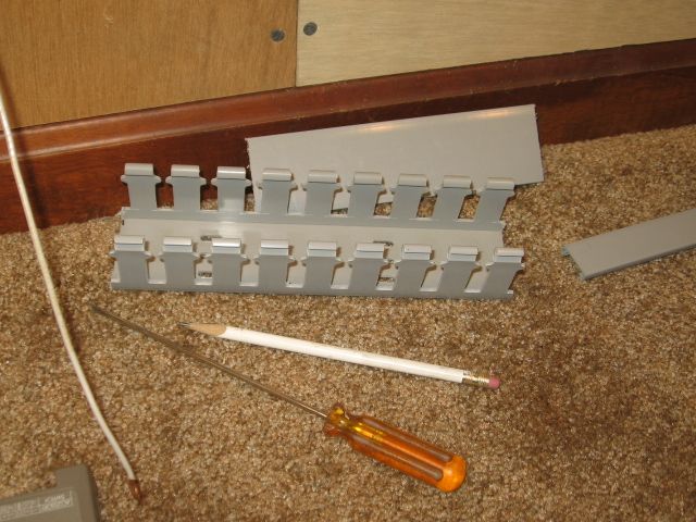
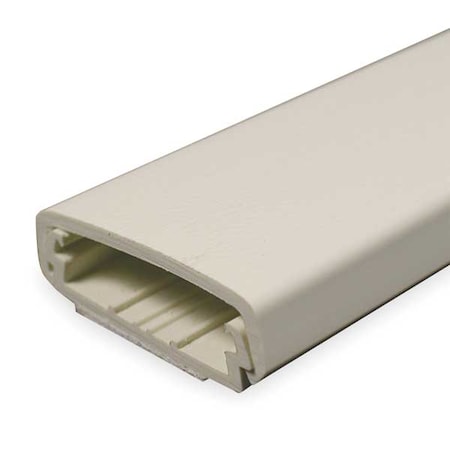
Cord channel or wire mould from your local big box hardware store.  They are typically plastic or metal, can be cut to length, and normally have tape on the back side for mounting to the plywood (or other surface).  Used to cover speaker wire or wiring for PCs or electronics.

I agree with the use of plastic wire mold.  It has pressure sensitive tape on the back side.  To make sure it sticks to the plywood apply Gorilla tape (thanks clem k) to the ply then attach the raceway to the tape.  Makes a very neat job and will stay put  forever. I've literally used 100's of feet of this raceway. TIP - If you use this method leave a length on string in the raceway in case you need to pull more wire through it in the future.  Sure saves a lot of time.  Just remember to pull a new piece of string with the new wire.


Last edited by wild mary

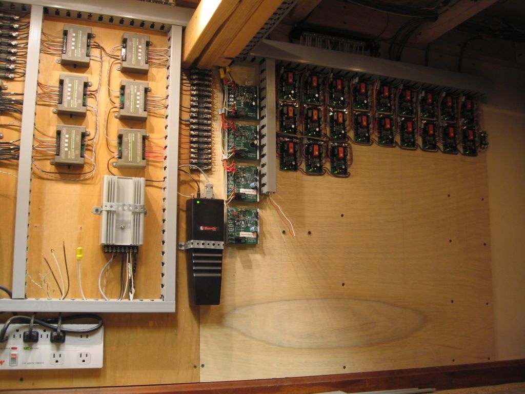
I would add the documenting the wiring scheme in a layout wiring book is "must do" for all but the simplest railroads.  I use an excel spread sheat page to record my numbered wire assignments for each panel - with liberal use of comments.  Also in the book are track diagrams with all turnouts and sidings numbered so I can correlate wiring numbers to the track diagram - eg: turnout 6 powered by switch motor hot lead 32, frog lead 33, turnout status bivalent LED indicator 34.   The wiring book takes a little time to set up but has proven invaluable.  


The first 2 photos are of the outside and inside of one of several control panels on my walk around style railroad - this one of the last town and hidden Middle Division staging tracks.  The panels are hinged downward for easy access.  The third photo is of the central power distribution panel with 3 DCC power district breakers and 5 staging loop auto reversers/occupancy detectors.  With thousands of feet of wire and a limited selection of colored wire - numbering the wires at both ends of the run was a must.


Ed Rappe  


IMG_0152

IMG_0154

IMG_0151

Attachments

Images (3)
  • IMG_0152
  • IMG_0154
  • IMG_0151
Last edited by Keystoned Ed

Brass/copper strips! I love it. Turn any flat into a homemade circuit board!

 I remember seeing layering of 4+ whole brass sheets, with insulation sheets in between, used in toys too. Cutting edges


Mike, nice house. My Grandpa G., and his sister Auntie Mike, used to combine skills for creating high, end dollhouses for the custom collector market. Lots of good ideas there.     

Add Reply

Post

OGR Publishing, Inc., 1310 Eastside Centre Ct, Ste 6, Mountain Home, AR 72653
800-980-OGRR (6477)
www.ogaugerr.com

×
×
×
×
Link copied to your clipboard.
×
×