Here are pictures of my lift bridge. I scratch built it with no plans just trail and error. 


TR18 posted:
TR18: I am intrigued by the interior horizontal stays running between the bents. I have not seen this previously in a model or a prototype trestle. Was this part of a prototype that you modelled? Not saying its wrong; I quite like it, just don't think I've seen it before.
EDIT: I take this comment back; just checked some other file pix and drawings, and I see they are there, maybe not quite as many, but they are there. My mistake.
Hope everyone does not mind me reposting again but a few people have given me some likes and asked me how I
built the 5 1/2 ft. curved bridge so here goes nothing. The first picture is the bridge cut out of fine chip chip board glued & screwed together with the box beam glued on the sides and flat black painted. The chip board is 1 in. double layered to end up about 1 7/8 in. thick. The supports are 1/2 in. (W) roof trusses and 1/2 in. sheet plastic glued together to make the legs. I glued the legs to a flat piece of plastic and glued in 1 in. (W) roof trusses as cross supports. Then I glued in (X) bracing for cross support then I painted them flat black. After I was done with them I showed them to some fellow model railroaders and they told me they are supposed to be tapered on the sides for lateral support. So the trestle supports I made are scrap and I wasted about $150.00 for nothing.
Choo Choo Kenny
![]()
Attachments
Very nice. Beautiful Job !
Where did you purchase the Plastice Steel Supplies from ?
Please keep us posted on your Bridge Structure Building progress.
Good luck, John
John if you are asking me Choo Choo Kenny I bought the box beam that went on the trestle from Scenic Express. I think the box beam is in 26 in. lengths but both ends have a 45 degree angle that I cut off. The supports some of the pieces are from Plastastrut and the flat plastic was a sheet that I got at Michaels. I bought a cutter table / shear from Michaels for scrapbooking and it had 6 different pattern cutter wheels for making designs in paper. I used the straight cut wheel and kept scoring the plastic until it cut the whole way through. I had tried to cut the flat plastic sheet on my table saw but it just kept cracking and breaking off pieces no matter how fast or slow I would go. I glued everything together with CA glue that I got from Scenic Express also. Once everything was together I painted it all with flat black $1.00 rattle cans from Lowes. When I make the new support legs I will taper the outside legs for lateral support (like on real trestles) and the legs will be made out of 5/8 in. (W) roof trusses and the cross supports will be 1/4 in. (W) roof trusses. When I built the first ones I never really looked at support legs on trestles and I had everything bass akwards. The legs were to small and the cross supports were to big. Thanks for asking and take care. Choo Choo Kenny![]()
Attachments
OMG, B&SRailroad, if that (!!!!!) is the effort with which you are starting your layout (!!!!!!!!!) I can well imagine where you are headed ! I particularly appreciate, as an accent to the spectacular structure, the way the stream/river comes into view from the left before is proceeds under the trestle. Interesting detail; different, in my experience, and a good one to remember. And the whole terrain, though not the type of landscape on which I have ever stood, seems very realistic to me.
FrankM.
Choo Choo kenny posted:
If that's your kind of scrape I'll take out the garbage anytime. I think it looks just fine, my elevated section needs something like that thanks for the how too.
Choo Choo kenny posted:
ChooChooKenny, Honestly, nothing has been "wasted." I think you are being too hard on yourself, and those fellow-hobbyists did you no kindness by telling you those supports were "supposed to be tapered." ![]() What good purpose could have been served by them stating that picayune factoid? I am surprised and disappointed a guest at your layout would have done so.
What good purpose could have been served by them stating that picayune factoid? I am surprised and disappointed a guest at your layout would have done so.
Plus, just look at those supports, esp. in situ, as we see them here. They look realistic and strong and handsome. I don't think many folks outside of real-life engineering and RR construction and the Picayune Club would have noticed any lack of upward-curving sides.
I think there is a point where one (esp. guests) should keep ones mouth closed, esp. if it does no worldly good to speak, and where we should find ourselves content with the work of our hands. I mean, it's not surgery. It's a train layout.
Rant of support over.
FrankM.
Rod Stewart posted:TR18 posted:
TR18: I am intrigued by the interior horizontal stays running between the bents. I have not seen this previously in a model or a prototype trestle. Was this part of a prototype that you modelled? Not saying its wrong; I quite like it, just don't think I've seen it before.
EDIT: I take this comment back; just checked some other file pix and drawings, and I see they are there, maybe not quite as many, but they are there. My mistake.
Rod
I definitely got that out of a book when I was doing research on trestle construction. However, it's been at least 10 years since I built that trestle and I can't be sure which book it was and I can't find the book.
Choo Choo kenny:
I am not a civil engineer but I think your fellow model railroaders may be wrong in their telling you that your structure should be tapered. The need for lateral strength is addressed by the cross members in each section. If you look at the steel structures used in the elevated subway systems, they are always vertical. As I recall, the main strength in a steel is it's compression strength and placing those beams at an angle would substantially reduce their support.
I think your support look great and most of us would be very proud to have such fine supports anywhere on our layouts.
Well done!
There are some really fine structures exhibited in this thread! Thanks to all who posted.
Happy railroading,
Don
Moonson posted:OMG, B&SRailroad, if that (!!!!!) is the effort with which you are starting your layout (!!!!!!!!!) I can well imagine where you are headed ! I particularly appreciate, as an accent to the spectacular structure, the way the stream/river comes into view from the left before is proceeds under the trestle. Interesting detail; different, in my experience, and a good one to remember. And the whole terrain, though not the type of landscape on which I have ever stood, seems very realistic to me.
FrankM.
Thanks for the kind words Monsoon. I'm building this with my 11 year old son, were not modeling anywhere in particular we're just doing it for fun and the learning experience, plus it gets him away from those video games. I always wanted to try my hand at building a trestle, it's a double track and it's not from any plan so it's not accurate, but I'm happy with it.
We'll post more as we move along.
Thanks again.
B&S Railroad posted:Moonson posted:OMG, B&SRailroad, if that (!!!!!) is the effort with which you are starting your layout (!!!!!!!!!) I can well imagine where you are headed ! ...FrankM.
Thanks for the kind words Monsoon. I'm building this with my 11 year old son, were not modeling anywhere in particular we're just doing it for fun and the learning experience, plus it gets him away from those video games. I always wanted to try my hand at building a trestle, it's a double track and it's not from any plan so it's not accurate, but I'm happy with it.
We'll post more as we move along.
Thanks again.
Good to hear on all fronts. We will, I am sure, all look forward to your next move along.
FrankM. (Moonson)
the talent on this forum surprises me. some of the bridges/trestles are just amazing. I have my favorites a few have been shown here in this thread. here's 2 just to name a few the first pic I wish I had the patience to build something like that . and the second one has been a favorite for a few years I just don't have the space for it . I just scrolled back thru there isn't a single bridge on this thread that isn't a masterpiece. there all awesome. ![]()
Attachments
Jhainer posted:Choo Choo kenny posted:If that's your kind of scrape I'll take out the garbage anytime. I think it looks just fine, my elevated section needs something like that thanks for the how too.
Don't scrap them, you can easily modify them to a tapered pier.
Don
My scratch-built Judy Jane Trestle. Full scale about 480-ft long, 104-ft over the lake, dual track, constant 1.9% grade, over 1000 pieces. I designed and built it according to the American Railroad Wooden Trestle Practices of 1913. See OGR Magazine Run 256 for design and construction details.
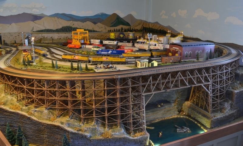
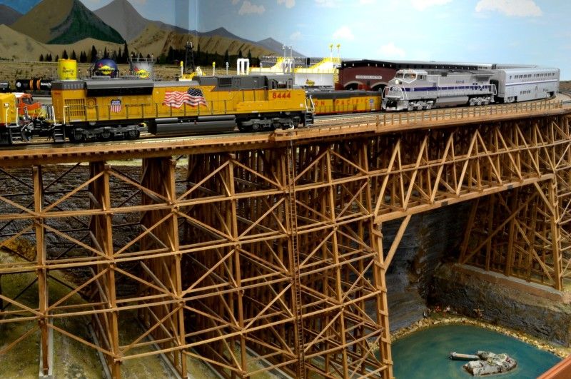
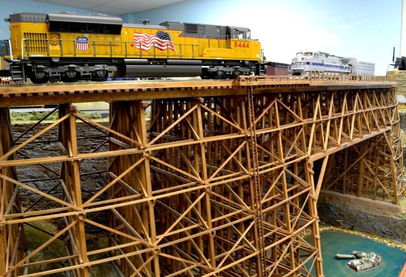
Alex
See what I mean, OGR world, just when you might have made up your mind you liked one of these bridges/trestles the best, Alex/Ingeniero No.1 shows up and gives us another masterpiece to consider = be blown away by (!!!!!!) Unbelievable!
FrankM
I would like to point out something about Choo Choo Kenny's concern about being told that the piers should be tapered; more often then not, this is a method used for wooden structures. For example, a roller coaster, or a wooden trestle. This is because of the flexibility of wood. If you ever watched the framework of a roller coaster as it goes by, you see the movement, and it's substantial at the curves. But one thing to observe, is the vertical supports directly under the the bridge super structure. This is what gives the bridge the load bearing strength to carry the direct weight of the train above. An example can be seen in Alex's, ( INGENIERO NO1), photos. I have seen many steel supports that are vertical, and many with tapered sides. Most often, the bridges with tapered sides tend to be rather tall. There are engineering schedules that determine the method for building a particular bridge depending on the materials used, the length of the span, the height, and the geography at both ends, and below.
Don
All this talk of tapered, non tapered is really interesting. The shape of the piers are directly influenced by not the bridge but the soil and the seismic activity in the area, not the bridge. Usually (and that is a very leading term) tapered piers has more to do with the stability of the materials used and the location in regards to soil conditions. The pier Kenny shows is perfect for a solid rock base / footing. It would even work for a pile driven pier if the piles were deep enough to insure stability.
For those on the west coast what do the piers look like for the Golden Gate or S.F. Bay bridges? On the east coast what do the piers look like for the Brooklyn, Queensboro, or Triborough bridges.
Anyhow my 2 cents worth, spend it wisely. The link below is to a easy reading engineering manual dealing with bridges. Interesting reading.
I love all the bridges, they ALL look terrific and the railroads they are attached too all look like a lot fun which is what this is all about, right? ![]() Russ
Russ
Thank you everyone for the likes and concern about straight vs. tapered legs. I am a jerk if all trades and a master of nothing. My father has always beat it into my head that anything you do had better be 110% perfect or it is a 99% failure. Even with that being said he would tell me someone else can always do it better, faster and cheaper than you so no matter how hard you try you will always fail anyway. I do not think of myself as a (RIVIT COUNTER) but I try to build things as close to reality on the train layout as I can. Those leg supports that were in the pictures have been cut apart to try to reuse but once the top and bottom were sanded on an angle to make the taper they were to short. They were thrown away a long tome ago and the new ones are being made from 5/8 in. (W) roof trusses and the cross braces are being made from 1/4 (W) roof trusses. I bought a rivet press to put the rivet details on the flat plastic that get glued to the (W) roof trusses so hopefully the new ones will look more realistic than the ones I cut apart. There are so many of you on here that I look up to Patrick H., GRJ, River Leaf Models, DOC, and many more that have helped and taught me so very much. I know my stuff does not belong on the OGR forum with the rest of you folks so from the bottom of my heart I say THANK YOU for all the complements on what I consider a failure. Take care and again thank you. Choo Choo Kenny![]()
Ingeniero No1 posted:My scratch-built Judy Jane Trestle. Full scale about 480-ft long, 104-ft over the lake, dual track, constant 1.9% grade, over 1000 pieces. I designed and built it according to the American Railroad Wooden Trestle Practices of 1913. See OGR Magazine Run 256 for design and construction details.
Alex
I have to admit Alex your article in run 256 of OGR gave me the inspiration to attempt building ours. Yours is truly a work of art.
VERY VERY NICE bridges fellows
Ken M
Attachments
Choo Choo kenny posted:I know my stuff does not belong on the OGR forum with the rest of you folks so from the bottom of my heart I say THANK YOU for all the complements on what I consider a failure. Take care and again thank you. Choo Choo Kenny
Kenny, your work is very nice and most certainly worthy to be on the forum. You are selling yourself short. Your dad gave you some conflicting advice. Giving you all would have been all the advice necessary. I look forward to seeing the revised piers.
Don
To:Kenny
That's something, I would like in a NYC Subway Structure type.
Thank you,John
John if you are asking me Choo Choo Kenny I bought the box beam that went on the trestle from Scenic Express. I think the box beam is in 26 in. lengths but both ends have a 45 degree angle that I cut off. The supports some of the pieces are from Plastastrut and the flat plastic was a sheet that I got at Michaels. I bought a cutter table / shear from Michaels for scrapbooking and it had 6 different pattern cutter wheels for making designs in paper. I used the straight cut wheel and kept scoring the plastic until it cut the whole way through. I had tried to cut the flat plastic sheet on my table saw but it just kept cracking and breaking off pieces no matter how fast or slow I would go. I glued everything together with CA glue that I got from Scenic Express also. Once everything was together I painted it all with flat black $1.00 rattle cans from Lowes. When I make the new support legs I will taper the outside legs for lateral support (like on real trestles) and the legs will be made out of 5/8 in. (W) roof trusses and the cross supports will be 1/4 in. (W) roof trusses. When I built the first ones I never really looked at support legs on trestles and I had everything bass akwards. The legs were to small and the cross supports were to big. Thanks for asking and take care. Choo Choo Kenny![]()
I as model railroader and a real life bridge engineer. I love seeing all these.
crood58 posted:I as model railroader and a real life bridge engineer. I love seeing all these.
Agreed - It is quite a diverse display of ingenuity and model engineering!
And thank you all for your comments on my trestle.
I would like to share the link to the 472-page book from which I obtained the data for my trestle. Yes, it is old (1913) but it is very interesting reading and is full of details.
Here is the link to the full 472-page version, "A TREATISE ON WOODEN TRESTLE BRIDGES"
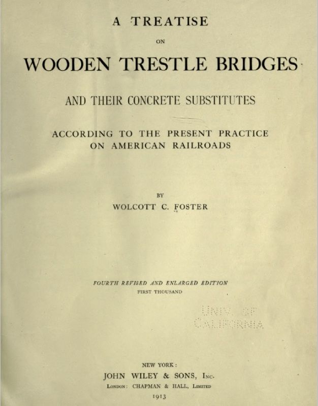
You can also buy the book from Amazon.
NOTE: Google provides several results for a search, and some are shorter versions.
Happy reading!
Alex

Add one.
Attachments
Gentlemen,
Way cool stuff everybody. Just got a nice Bridge for my Christmas layout myself, course mine is the Hellgate 305 Tin Plate Bridge! In fact UPS delivered it this morning, I think I was awarded 1% stock in UPS, because of contracting them to deliver it, the other two items that fit on the truck, I believe were mine also.
Attachments
From the very good, the excellent to the incredible they are all here. A most enjoyable post. Hope to post my creations here soon. Latest bridge is a replica of Carrolton Viaduct in Baltimore. Americans oldest RR bridge, built in 1829 and still in use today. Anyone else modeling it?
Jhainer posted:
The original mock up for this bridge was a 2 arch version. It looked very good and was only about 14" long. Will post picture later.
![]()
Attachments
"on what I consider a failure" Kenny there is no such thing as a failure, only WORKS IN PROGRESS! ![]() We have all REPLACED parts of our railroads. Hopefully each time it works / looks better. Love dem bridges! Here's some I've done. Russ
We have all REPLACED parts of our railroads. Hopefully each time it works / looks better. Love dem bridges! Here's some I've done. Russ
Elevated traction line on a 2 rail O scale club layout

Work in progress on30 Lobato trestle

Two O scale Plasticville bridges modified to be the Rio Chama bridges in Chama.


