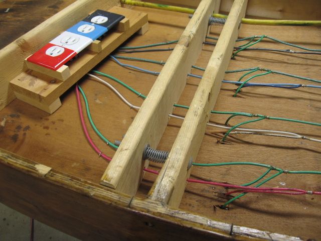
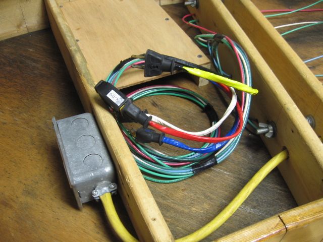
Building a modular layout for post war equipment. Need recommendations for cable connectors between modules. Layout will have 17 switches, 18 blocks, post war accessories (97, 397 & 497 coal loaders; 164 & 364 log loaders; 362 barrel loader; 165 crane), 14 uncouplers & various lighting & signal circuits spread over 6 modules. Therefore, there will be a large number of connections between some modules. Will appreciate recommendations & sources (suppliers). Thanks,
Replies sorted oldest to newest
Some use telephone type jacks. But I prefer Jones plugs. http://www.cinch.com/products/...jones-plugs-sockets/
They are available in all types of configurations. And unlike phone jack types, they can handle a lot of current.
Trailer light connectors would work for the heavy wire connections.
You should also look at Molex connectors- They come in a lot of sizes and shapes from 2 to 12(or more) connections, and can handle the current that O gauge stuff needs. just google "Molex" and you'll get lots of hits. They are available from just about any electronics vendor-- Ebay is a good place to find them.
We use Anderson Power Pole connectors our 26 module modular layout.
I'm using Molex connectors on the layout I'm building now--so far, so good. I got mine from Mouser. They are very inexpensive per connection, which is nice when you need a lot of them. I have done 30 or 40 so far, and they are working well. Have probably another hundred to go. A few things I have learned:
1. Do your homework before you order, there are several different pin types and plug types, not all compatible.
2. If you order from Mouser, don't get the contacts in the "cut reel." The reel is meant to be fed through a machine and you can't cut them off yourself and get the tolerances you need.
3. It's important to insert the pins into the plug housing facing the same direction--that is, so the seam on the rolled pin is always at, say, three o'clock. This is because the pins seem to like to lean one way or the other in the plug housing, and it can be hard to get the thing plugged in if the sockets in the receptacle housing are leaning to, say, 9 o'clock (if that makes sense).
4. I bought the Molex crimp tool. It makes pretty crimps every time. Worth it, in my opinion.
Building a modular layout for post war equipment. Need recommendations for cable connectors between modules. Layout will have 17 switches, 18 blocks, post war accessories (97, 397 & 497 coal loaders; 164 & 364 log loaders; 362 barrel loader; 165 crane), 14 uncouplers & various lighting & signal circuits spread over 6 modules. Therefore, there will be a large number of connections between some modules. Will appreciate recommendations & sources (suppliers). Thanks,
Take a look at the National Capital Trackers module specifications. They went to Anderson Power Pole connectors. They use blocks, but you could just use sets of them connected. I believe the North Penn O Gaugers also use the Anderson Power Poles. Module specs on their website.
Both run Legacy and DCS. The trackers did some extensive testing to minimize power and signal loss. They display huge sets of modules. They did away with Jones connectors due to signal issues.
The Pittsburgh group goes a simpler route with good performance. They also put up huge displays. (sorry, don't recall their proper name)
I've used Molex connectors many times in the past, but the Anderson Power Pole connectors are much higher quality and less likely to create issues in the future. Molex is not good for anything that will be connected and disconnected a lot.
The Pittsburgh group goes a simpler route with good performance. They also put up huge displays. (sorry, don't recall their proper name) Two groups. Pittsburgh Independent Hi-Railers, and TCA associated, Fort Pitt High Railers both use the same, controversial connection method. Note that there is identification. 

Male/female connectors are polarized, 15 amp capacity. Wiring is 12 gauge stranded. There are (4) main tracks, recent set-up at the Pittsburgh Home and Garden show was 40' X 40' (160ft Square/sort of). Lesser grade receptacles tend to loosen and cause problems, we have upgraded to Spec grade/better quality receptacles in most cases.
Thanks, Mike for coming in on this. I apologize for not remembering the clubs name. I enjoy your posts and pics and videos of the events.
Staying on the simple approach, LCCA standards for their module uses an 8 conductor molded trailer extension cable(male and female ends) I have been using some for a year now. No Legacy issues. Had to shoot some lube on the pins as they were too tight when connecting\disconnecting.
I am using the Power Poles for track power on a layout for a museum display. We had to divide it into sections(modules) for ease of occasional transportation. It's 11 x 17 and 3 track layers. Not sure yet on the accessory harnesses. The original builder used DB15 male and female for multiple cat 5 cables.
Thanks to all who replied to my post. I looked on line at several of the recommendations. I was not able to determine how many circuits a single Anderson connector can make. I need multi circuit connectors. As an example the control panel which will plug into the layout via connectors has over 100 circuits & there will be as many as 60 circuits between some modules. The layout will be assembled & disassembled only once a year so intensity of connect & disconnect is not a major issue. Molex may be a possibility. I have some older Jones plugs with 30 connections plus (which apparently are no longer available) but not enough for the entire layout so I have to supplement with another brand.
Take a look at allied electric. They sell Harding plugs. There are many styles. http://www.alliedelec.com/hart...9021646921/70070324/
Thanks to all who replied to my post. I looked on line at several of the recommendations. I was not able to determine how many circuits a single Anderson connector can make. I need multi circuit connectors. As an example the control panel which will plug into the layout via connectors has over 100 circuits & there will be as many as 60 circuits between some modules. The layout will be assembled & disassembled only once a year so intensity of connect & disconnect is not a major issue. Molex may be a possibility. I have some older Jones plugs with 30 connections plus (which apparently are no longer available) but not enough for the entire layout so I have to supplement with another brand.
I believe the only way to accomplish your task would be to use the Anderson for track power and accessory power (or others) and use D-subminiature connectors for switch and control wiring. The D-sub will handle a max size of 20awg, but for practicality, you talking 23 or 24awg and bundling Cat5 cables to build the large cable. They won't carry track current or switch coil current, but ok for other loads.
One vendor I found to illustrate is in the links below. There are solder cup and crimp DB25 & DB50, but they have these DB25 field connectors in male and female.
The D-Sub connectors were used by the builder of a layout, that I am helping to restore for a museum, that I previously mentioned. I will have to tackle this same problem soon. (Only 15 or 25 wires per connector though)
Learning the technique of soldering or crimping the small wire to the connector makes these field version connectors look appealing, but I am sure they were intended for temporary use.
The Blanks with the crimp pins look like the option I would use for DB25 or DB50. get the special crimp tool and small wire stripper and your ready to create a cable.
Reducing the load(led's for lighting and such), localizing accessory control buttons are factors to consider.
I am out of ideas now. Let us know how you solve this.
The Anderson Power Pole connectors are modular connectors, you stack them to build a connector of any number of connections.
I like Carl's idea of DB connectors for the low current wiring, if you pick up a crimping tool, you can whack them out quickly, no need for Anderson connectors for low current wiring.


