Post 76          3-18-2021

A Lionel 6-8562, GP 20  -  Latest Diesel Roaming the Layout

A couple of weeks ago I made a rare eBay purchase, a Lionel Missouri Pacific GP 20 Diesel.  I liked it for its low hood, short nose and blue color.  I think it is distinctive and more handsome than the GP 7 and 9 that lack the low hood.  It is a 6-8562, with one motor and traction tires.  It looks fine on my 027 curves and runs very well on 027 track and 31 Marx metal frog 1590 switches.

Lionel 6-8562, GP 20 with repainted Missouri Pacific SP style Caboose (probably my first caboose repaint job) in background

IMG_0392

IMG_0395

IMG_2457

IMG_2261

IMG_2262

You can see the great view forward from the cabin with the short nose up front, a much better view than of my last favorite diesel, the RS3 which I am still looking for.

Charlie

Attachments

Images (5)
  • IMG_0392
  • IMG_0395
  • IMG_2457
  • IMG_2261
  • IMG_2262
Last edited by Choo Choo Charlie

Post 77          6-19-2021

Reviving 1930s Lionel 238 Streamlined Torpedo Locomotive with Marx motor and Tinplate Tender

I have owed a Lionel 238, the Loewy’s 1936 designed, torpedo streamlined body and old style metal tinplate tender for several years, origin unknown.  It needed a motor and I found an old Marx four wheel one from a Marx 999 that seemed to work and fit.  The Marx motor did not have the mount and two front wheels like the 999 does.

I have looked into adding a pair of wheels on the front and on the rear to make a 2-4-2 but could not come up with "something" that would work but believe if I can find a mount and set of wheels from a 999 they would work.  They can be added later so for now I am going with a 0-4-0, which will run with no derailments of front or rear wheels.

IMG_4142


A metal mount was made for the rear and front of the motor into the engine and J B Welded them in.  Also made was a small metal tube to hold the head light, which is a 12v mini Christmas tree bulb, bulb holder, wire and socket.  A small hole was drilled into the top of the metal hole to let hot air out and added a small piece of red clear plastic to make a little red glow on the stack.  A locomotive coupler was installed.

The coal tender had a set of Lionel trucks, one with a Lionel coupler, were installed and a tender coupler was added to the front.

IMG_4148


Motor holder shown below

IMG_4149


Marx 999 motor and coal tender coupler shown below installed

IMG_4145


The engine and tender were painted with flat darkest gray spray primer and then covered all with clear glossy paint.  A small metal strip was labeled with "L I O N E L "letters and sprayed with clear.  This was installed were the original engine had a strip labeled "Pennsylvania".  I decal-ed the engine and tender as "Pennsylvania" and used the side strip to show "Lionel" as the manufacturer not the fictitious "Lionel Lines" as Lionel had done.  The decals were sprayed with clear glossy paint to seal them on.


IMG_0434

This picture shows the head light and the Red lighted smoke stack glow from the fire box

IMG_0440

Ice Station Pic 11-16-2023 2023-11-16 003


IMG_0438

I wanted to also pull Marx tinplate cars as they are lighter and more typical of 1930s trains.  The Torpedo tin coal tender got Lionel old style couplers so I made a tiny adapter from a paper clip shown below, to allow pulling Marx spade coupled cars.  It simply has a loop to be held by the pin of the coupler.

IMG_0453


This shows it hooked up to a Marx boxcar.

IMG_0457


Below is my Marx cars tinplate train being pulled with the new to me Lionel 0-4-0 Torpedo stream lined steam locomotive.  This is an easy pull for the low powered Marx 999 style motor in the Torpedo.

IMG_0456

This was a fun project and is my first Torpedo Locomotive.  I now have a late 1930s streamlined torpedo loco and tinplate metal tender.

Charlie

Attachments

Hide
Images (10)
  • Images Title Caption Optional insert into post body IMG_4142 Title Caption Optional insert into post body IMG_4147 Title Caption Optional insert into post body IMG_4149 Title Caption Optional insert into p
  • IMG_0453
  • IMG_0457
  • IMG_0456
  • IMG_4149
  • IMG_4145
  • IMG_0434
  • IMG_0440
  • IMG_0447
  • IMG_0444

Attachments

Images (8)
  • IMG_4142
  • IMG_4148
  • IMG_4149
  • IMG_4145
  • IMG_0434
  • IMG_0440
  • IMG_0438
  • Ice Station Pic 11-16-2023 2023-11-16 003
Last edited by Choo Choo Charlie


The next one is a 4-6-4 Lionel 2065, a skinny Small Hudson with a Santa Fe boiler front and was designated good for O27.  It has Magna-traction and was built in 1954-56.  I have some long Lionel streamliner coal tenders and also have made a long Vanderbilt coal tender that look better with this long engine. IMG_1059

Excuse my ignorance but did you paint the valve gear gold on this engine? Or is it a camera trick? I don't recall ever seeing one like this before.

Post 78          8-11-2021

Engines Purchased with Previous Owners Modifications

Three Train Show purchased Engines, with Previous Owners Modifications are reviewed below.


Lionel 2065 Baby Hudson With Gold Painted Running Gear

Ben:  Thank you for the question about my Lionel 2065 baby Hudson.  I bought the engine only at a TCA train show at Millerville School, in Baton Rouge, LA in 1999 and it came with the gold colored running gear.  It was painted gold by a prior owner.  For some reason I have not run it or the Lionel 2046,  bought about the same time, much until the last year to two.  I like the 2046 a little better as it is not a narrow looking as the 2056 but runs and pulls the same.  I buy all used trains and once in awhile they a have been "improved" by prior owners.

IMG_1059


Gold running gear Lionel 2065 with new Homemade Longer Vanderbilt Coal Tender

IMG_0903

Lionel 2025 with Enclosed Cab and White Wall Painted Wheels

A Lionel 2025 was purchased without coal tender at a train show at the Astro Hall train show in Houston in 2002.  The Lionel 2025 came with a homemade enclosed cab and White Wall painted wheels.  I left all in place.   Recently I installed a coupler for a coal tender on the front of the loco to allow a oil tender to be pulled by the front of the locomotive.  It is now used as a Cab Forward locomotive with a oil tender.

Lionel 2025 with Enclosed Cab and White Wall wheels


A working Head Light and Marker Lights were added to the cab to allow use as a Cab Forward locomotive.  The camera flash brings out all the imperfections.  It looks like the original owner used the rough side out on small piece of 1/8 inch Masonite particle board.

IMG_0587


Lionel 2025 enclosed cab loco as a Cab Forward loco with oil tender

IMG_1100


Lionel 4-4-0 General and Coal Tender- Engine has Home Crafted Wooden Cab and Cow Catcher

Here is a Lionel 1862, 4-4-0 General and coal tender that came with a homemade wooden engine cab and cow catcher.  It was purchased this way, at a TCA Train show in 2018 in Ponchatoula, LA and was the reason I got it for an inexpensive price.   I thought a prior owner did a lot of work and a good job on the wooden modes.  The roof is a little rough or more realistic.  I do not know if real 4-4-0 General style locos had wooden cow catchers or not, but probably not.

General w wood cab 11-7-2018 2018-11-07 004

General w wood cab 11-7-2018 2018-11-07 009

IMG_0575

You never know what you might find at a train show.

Charlie

Attachments

Images (5)
  • General w wood cab 11-7-2018 2018-11-07 009
  • General w wood cab 11-7-2018 2018-11-07 005
  • General w wood cab 11-7-2018 2018-11-07 004
  • IMG_0575
  • IMG_0587
Last edited by Choo Choo Charlie
@Mannyrock posted:

Hi Charlie,

I don't mean to hi-jack this thread, so just refer me to the electric board if appropriate.

Your inner large oval has the "X" configuration in the middle of it, using just four switches.

Didn't this create a "reverse loop."?   

How did you handle that?

Thx,

Mannyrock

Not sure what you mean.  Unlike 2-rail, a return loop does not create a short circuit in 3-rail.

Well,  I guess I thought that if your engine is running clockwise around an oval, and then enters a turnout that puts it in the "X" part of the layout which is situated in the middle of the oval, and then follows that leg of the X across the crossroad, and then comes out on the other side of the oval and enters that oval such that it is then traveling counter-clockwise on the oval (i.e. suddenly traveling in the opposite direction on the oval), then that would cause an electrical problem or a stall.    I would very be happy to know that I am wrong.   :-)     

I mean, your engine is suddenly running on the original track, but in the opposite direction.

Does the presence or absence of an E switch have anything to do with this?

Thanks,

Mannyrock

@Mannyrock posted:

Well,  I guess I thought that if your engine is running clockwise around an oval, and then enters a turnout that puts it in the "X" part of the layout which is situated in the middle of the oval, and then follows that leg of the X across the crossroad, and then comes out on the other side of the oval and enters that oval such that it is then traveling counter-clockwise on the oval (i.e. suddenly traveling in the opposite direction on the oval), then that would cause an electrical problem or a stall.    I would very be happy to know that I am wrong.   :-)     

I mean, your engine is suddenly running on the original track, but in the opposite direction.

Does the presence or absence of an E switch have anything to do with this?

Thanks,

Mannyrock

Don't worry - be happy.  No short is created, and the e-unit has nothing to do with it.  It's the magic of AC.  Remember that the two outside rails are common.

Here you go...

https://www.youtube.com/watch?v=3UMVVewd3Nw

Last edited by Mallard4468

Post 79          2-11-2022      revised 9-21-2022

NO-OX-ID A-Special Electrical Contact Grease Treatment for My Layout Track to Prevent Sparking and to Eliminate Track Cleaning FOREVER !

This post is a  review and tells of my application of NO OX on my track and engine wheels.  A complete detailed explanation of what of NO-OX-ID A Special is, its history and application instructions (also summarized below) can be found on the below OGR topic link

https://ogrforum.com/...7#159660139094824137

An excellent you tube video below explains and shows how to use non polar Mineral Spirits to clean track and how to apply NO-OX-ID A Special to treat tracks to eliminate track cleaning forever.

https://www.youtube.com/watch?v=lBYxjcTWCB0

Testimonies for NO OX from 10 years ago

https://forum.mrhmag.com/post/...o-ox-thread-12189685

Other MRH Posts on NO OX

https://model-railroad-hobbyist.com/node/7519?page=2

https://model-railroad-hobbyist.com/node/7169

Much was found on NO OX and its as least 58 year history of use on model train tracks to improve operation, eliminate sparking and track cleaning forever.  Sounds good doesn't it?  NO OX has been successful for many model railroaders, for many years.  Many others have determined it failed and most probably tried it before the latest instructions, that emphasis the use of very little NO OX and special instructions for how to apply it, and how to handle its use with engine traction tires.

I bought a 2 oz jar on eBay and followed the 10 step application that is condensed below.

First, all the train engines and cars were removed from the layout on 12-3-2021.  Then, all the train track and engine wheels were cleaned.  Fine sand paper and Mineral Spirits were used for the track.  Track that had engine skipping was fixed.  I checked all my locomotive for black gunk on the wheels with most being on the lead truck of steam locomotives and removed the gunk by scraping with an old pocket knife.  I then clean all engine wheels with mineral sprites.  This took a long time with over 40 locos.  I did not clean any coal tender or car wheels.

Second, NO OX was applied on 12-6-2021, with a very thin smears on my finger, and rubbed it on all rails.  I did not apply enough to see any residue of globs of NO OX.  Next all of my locomotive, expect the three locos with traction tires, were run on all tracks to coat all the wheels with NO OX.  Many slipped and had to be helped to make it around a loop.  Engines were run on all the loops and track I could.  This took a good amount of time as there are 40 or more locos. Each loco was not run for 2 hours recommended by some, but were let to make several loops and ran on all track with one or more locos.

I then removed the last engines and rubbed down, (not scrubbed)  the track with a clean tee shirt .

The track was allowed set for 24 or more hours.  Then, an old clean tee shirt was used to gently rubbed, not scrub, down the all track again and some black was seen on the shirt rag.

There was a little slipping on a couple of my Lionel 2-4-2, 248 style plastic body engines which required slow operation to reduce slipping.  Later, I ran my Christmas train, with a Lionel 44 switcher and 6 cars and some slipping occurred.  My operating car train, with a Lionel 2035 and 6 heavy operating cars also slipped some on start up.  I wiped the track off again with a tee shirt and slipping ceased.  My passenger car train, with lighted 2400 series cars and two dome cars, pulled too much amperage with a 2035 so I changed it out with a Lionel AA 2024 UP diesel and removed one dome car.

I then ran trains and some still slipped when pulling cars mostly,  I ran the light Lionel 2-4-2 plastic engines without cars at first due to slipping.

Later, a very small amount of NO OX was applied on the wheels of the engines with traction tires.  NO OX was not applied any traction tire.  After setting 24 hours, the metal wheels were wiped down with a tee shirt rag.  The traction tire engines run great with the NO OX treatment on the track and have super slow speed operation.

IMG_1093

One thing noted was all trains and engines could be operated and switched much slower than ever before.  This was not noticed before, even after just cleaning the track.  Slow operation was not possible before with my O27, 31 Marx switches, conventional control layout and mostly post war locomotives .

As of the last week in January, the only train that will slipped occasionally is my Lionel 2-4-2, 248 plastic body engine with 4 giraffe cars and caboose.  I now run it with a 2035.  Slipping is very rare now.

I am very pleased with the overall experience with NO OX.  Operation is much smoother and trains can be run at much slower speeds and with very few skips and no sparking.  I can not over state how much better my layout operates.  A few track sections were found with poor track connections, the cause of those skips.  The final thing to find out is how long the track stays clean and good operation continues.  NO OX is supposed to eliminate track cleaning forever!  We will see if that is a fact for me.

After applying NO OX to your tracks, do not ever use any cleaning solvent like Mineral Sprites, alcohol, Goo Gone, you name it, or sandpaper or any other abrasive to clean your track as you will remove the NO OX and you will have to repeat the application regiment all over again.

Some railroaders complain about rust on the track rails.  I do not want rust on the tops of the rails and remove it with fine sandpaper.  I do not mind rust on the sides of the rails as it looks realistic to me as I never have seen a real track rail, shinny.  The NO OX should eliminate rust on the rail top and it can be applied to the sides of the rails if no rust is wanted there.

I have turned into a NO OX fanatic.  I have applied it to my NiMH batteries and chargers and battery radios like head phone Sony Walkman AM &FM batteries and cell terminals.  I have also treated the land line telephone connections between the phone line and the phone and the base and hand held unit and static has decreased or has been eliminated.  I have also used NO OX on some of my audio RCA plugs, some of which tend to get white powdery residue and speaker wire terminals but have lots more do as time permits.

This week, 2-11-2022, the 31 Marx 1590 switch track contacts were cleaned with fine sand paper glued up to make two sided sand paper.  It is used by pulling in both directions and an then applying a little NO OX, with a small thin piece of card board, to both sides of the contacts to keep sparking down and contacts clean.  I also applied NO OX to the contacts, of my two relays that control my automatic 2 trains operating on 1 loop track systems, with isolated track section triggers.  They have not been reliable for several years, but work much better now.

Picture of Marx 1590 switch rail copper contact strip.  The two rivets below the copper contact are the contacts for the center rail. IMG_1094


Picture of two sided fine sand paper strip cleaning contacts IMG_1096


This post will be up dated in the future, when experience with the NO OX treatment has been had, after months or years, to determine if NO OX really makes track cleaning a thing of the past !  Meanwhile the trains are running better and slower than ever before.

NO-OX Charlie

Attachments

Images (4)
  • IMG_1093
  • IMG_1094
  • IMG_1096
  • IMG_1098
Last edited by Choo Choo Charlie

I came across probably the same source as you did, on the No-Ox recommendation, about a year ago. I have an O27-type layout 4 x 24, with 2 concentric loops, powered by a KW. The switches are all 1122's. I run both PW and RailKing engines (no DCS.) Before I applied it, I meticulously cleaned as much old grease & residue off as possible, then laboriously "lightly" coated all the rails with No-OX, and then wiped them off later, as per the instructions. (The guy independently promoting the stuff gives an EXACT prescription for how to apply & remove excess.) I DO think it has helped. I still get sparking at some of the switch junctions as wheels go over them, but that was happening previously to No-Ox. I think I have noticed better slow-speed running as well.

Post 80   4-19-2022  Revised 4-20-2023

Videos  - Showing Two Sets of 2 trains Running on 1 track, and 5 trains Running

Here are some videos of two loops of 2 trains running on 1 loop track, and total of 5 trains running.  I got around to finding out why my 44 year old relayed 2 trains on 1 track of two loops did not work.  The insulated track sections, making the relays trip, both were grounded.  On the inside loop, the homemade tooth pick with a ring of wire insulation track pin was squeezed, grounding it.  On the other, there was a steel pin in the insulated outside rail that should have been a fiber pin.  Both track sections were located on the seam where the two train boards were separated for storage each year.  I used a Dremel with fiber cut off wheel the cut through both grounded track sections to reinstitute the isolation.  Fixing the insulated track sections and the recent NO OX treatment on the rails made the operation super good.

I had to try different locomotives and number of cars it took to make the speeds close to the same.  I wound up using four non smoking Lionel 2016 and 2018, 2-6-4 locos.  The similar Lionel 2026, 2-6-4s ran slower, as they had smoke generators.


Video below shows the inner and outer loops of the Main train board operating counter clock wise, with each having relays operating, to run 2 trains on each loop  Note:  I had to add another missile car to one outer loop train to get them to stop via the relay.


Videos below show four trains on the Main train board operating, with 2 trains per loop,  Inner loop is running CW and Outer loop CCW, and the Operating car train running on the New train board giving 5 trains operating.  Note:  The two, 2 trains on 1 loop trains, are not requiring the relayed system to perform their duty as I was able to run these four, 3 car trains, for at least 10 minutes without its assistance.


The video below shows one, 2 train on one track loop, on the Main train board inner loop going CW.  The other, 2 train on one track loop, is operating CCW on the outside loop of both the Main train board and the New train board.  This can only be done going CCW due to availability of the relay controlled track section and insulated track section.  This is not the case for CW running.  Note at the end of video,  Schnoodle dog Beau is checking out train action of which he is very interested and thinks trains are alive.


Video below show both Main Train Board loops with 2 trains per loop running as Slow a possible and with most layout turned on.  Note:  All my videos show the trains running faster than they really were running.


Video below shows Five Trains Running with two Main train board loops with - 2 trains on 1 track  and 1 train on one loop on new train board

Hope you enjoy.

Charlie

Attachments

Videos (6)
264_0496
264_0488
264_0489
264_0493
101_0500 (2)
2 Trains on 1 Track video 4-18-2022 2022-01-01 003
Last edited by Choo Choo Charlie

Fellows

Thanks for the kind comments.  The layout is running better now than ever.  Two pairs of 2 trains on 1 track has never been this reliable, just like running one train per loop.

I even had 3 trains on 1 track (on the long outside tracks of both train boards) for about 3 minutes, drawing about 4.3 amps on one LW, until a derailment!  It will never work well since there is only one isolated track section and only one train can be slowed down by relay.

Charlie

Last edited by Choo Choo Charlie

Post 9   6-25-2016,   revised 1-8-2022

Turntable with pit Construction & Operation - Homemade and Scratch Built and Inexpensive ($10 !)    How to Build any Size Turntable with Pit for $10

The center piece of the layout is the scratch built, inexpensive turntable and roundhouse.  Designing and building the turntable was the most fun part of the whole train layout for me and well worth the time and effort as it provides much operation interest and fun.  The Turntable was built during the initial layout construction in 1977 in Kingston Jamaica.

The turntable can be built the same way I made this one for any size of table one needs and for any gauge of train track.  It can be rotated by crank, pullies and belt like mine or rotated with an junk electric DC battery drill or screwdriver motor powered by a small, cheap DC HO transformer and located any where on a layout.  If your layout is already built, the turntable can be more easily built in a 2 or 3 ft or so, square module, in your work shop and then set into the layout.  The turntable can be detailed from Toy 027 to scale, depending on the builder desires.
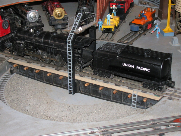
IMG_0912

Turntable Description and Construction Details

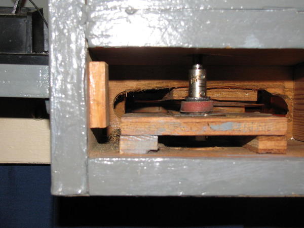
The turntable rotates on a 6 inch diameter (8" might be better for a larger TT) Lazy Susan, metal turntable ball bearing unit and rotation is by a hand crank driving a pulley beneath the turntable using a spare or used clothes dryer drum belt.  I purchased the 6 inch diameter lazy Susan turntable ball bearing unit, for about $5, at a hardware store.  I had a spare dryer belt as I lived overseas and appliance parts are hard to get.  Track alignment is the realistic, "line it by eyeball" method and roundhouse  track selection is by a rotary switch.  A momentary push button switch is used to activate the selected RH track and the TT track.  A light in the TT shack comes on with the activation of the TT track and indicates power is on.  The turntable has a pit as that is more realistic and better looking in my view.  It would have been easier to surface mount a Lazy Susan bearing on the train table like the Lionel TT, but seeing it made a pit a must have.

Location of the control panel and the turntable, with hand crank, should be fairly close to each other for two reasons.  One is the use of a clothes dryer belt will require it to be close.  The other is it is helpful for the engineer to be close at hand to correct derailments and to see the turntable as eyesight is used to align the TT and the tracks.

The homemade turntable can be belt driven with a hand crank like mine or can have an old battery driven screw driver as power and the TT can be located anywhere.  More details later in this post.


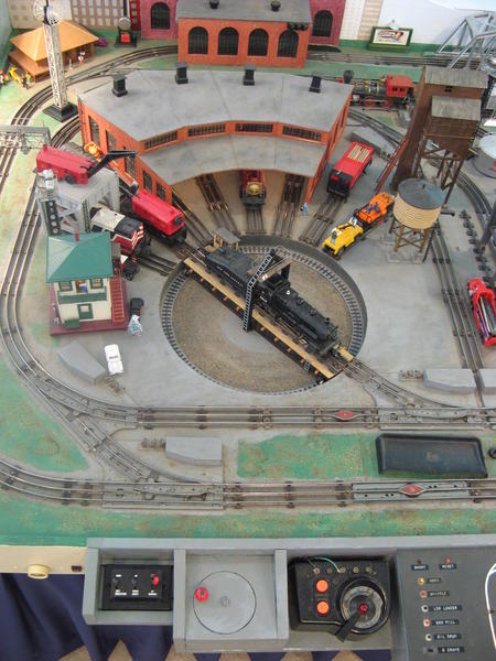
Picture of TT with TT crank (red knob) and Control Panel -  Picture shows the track with crane car and caboose align with the TT and the off trackTrain Lots 5-10-2016 272

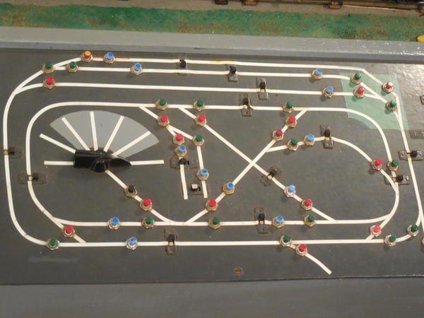
Picture of main control panel track diagram with selector rotary switch (black knob with pointer) to select track for transfer of train from TT to spur/roundhouse track.  The black push button momentary switch, below the rotary selector switch, controls power to the selected track and the turntable track.Train Complete 1-17-2015 152

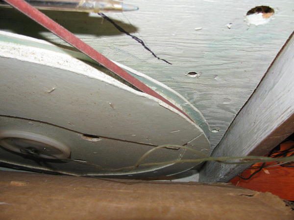
Two pieces of 027 track or 17 5/8 inches was chosen for the turntable bridge length.   17 5/8 inch diameter will handle all of my engines and coal tenders at the time I built it.   Two more inches of length would have been better and handle my later bought larger engines and coal tenders but space was at a premium   I cut a  17 5/8 inch diameter circle in my  3/4 inch thick particle board train board using a sabre saw and used the ¾ inch thick, 17 5/8 inch diameter cutout as a pulley by adding a rim of 1/8 inch Masonite around both edges as pulley flanges sticking out about ½ an inch.  

Most of the work on the TT was done with my train board section standing on edge, leaning against a wall.  To build a TT for an existing permanent layout on legs would require lots of work under the table and looking up.  In such a case one might want to build a two foot or so module to construct the TT and install as a unit.

A recessed ring around the turntable hole, about 1&1/2 inch deep, was installed on the bottom of the hole and a 1/2" plywood bottom was added.  A 3/8" hole was centered in both TT bottom and the pulley.   A 2"x 2" x 3/4 inch block was drilled in the center to take a 3/8 threaded hollow lamp rod.  The block and rod were mounted about 1 inch from the rods end and drilled for a 2 inch long finish nail.  The block was glued and screwed to the pulley in the center.

A 6" lazy Susan ball  bearing (Ace or Home Depot for $4) was screwed to the top of the pulley.  Four 1 inch diameter holes were drilled through the pulley for the screws on the other flange of 6” lazy Susan bearing.  These holes allow the bearing to be screwed to the underside of the pit bottom.

The lazy Susan bearing will hold all the weight of the pulley and take the side thrust from the clothes dryer belt.  The 3/8” threaded hollow lamp rod allows thin, flexible twin wire to feed power to the TT bridge and to secure the bridge to the pulley beneath the TT pit.

The 3/8" dia. threaded hollow lamp rod was installed through the pulley and the rod was pinned block on the pulley with a nail.  The rod was measured to the length needed to go through the pulley, block, TT bottom and to the top of the TT bridge minus a ¼ inch, sawed off, and a hole drilled through the bridge to be able to pin the rod to the TT bridge to be built.

A pair of wires were run up through the 3/8" dia threaded hollow lamp rod and soldered to the outside and middle rail of the track that was put on the TT bridge.  Some slack was left in the wire and a type of disconnect like a plug or spring clips ( I used two electrical connectors cut from old 9v batteries) was installed to allow removal of wire to unwind the wire if it gets twisted too much (I also try not to keep going is one direction too much!)


Picture of 17 5/8"dia. Pulley under Turntable with Clothes Dryer Belt and wires from TT BridgeIMG_0006

A spare electric clothes dryer belt, that is about 3/8" wide and 1/8"thick and about 8 to 10 feet in total length (not diameter) ,was used to move the TT.  This is the size of most any make of clothes dryer.  The belt  is super strong, as after all it must apply power to 20 pounds plus of wet cloths in dryer drum, from the motor to the drum.  

I made a hand crank out of a 6" long 1/4" carriage bolt as the driving pulley with disk and knob held on to the disk with a Tee nut and locking nut as the crank.   Over sized Tee nuts were used for shaft sleeves for the shaft, top and bottom.  A small pulley was made for the shaft from a ¼ inch ID radio shaft coupling and two brass grommets soldered together to make a Vee to give more bite on the belt by the small shaft.  This Vee is necessary to keep the belt from slipping on the small diameter shaft of the crank and also make the diameter larger than the shaft.


Picture of Hand Crank Vee pulley made from radio tuner shaft coupling (seen with the set screws showing) and brass grommetsIMG_0024

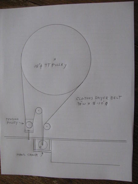
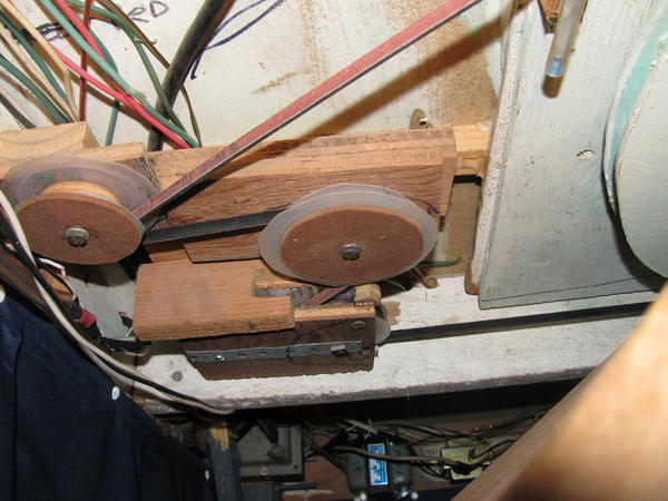
A 2" dia. take up pulley assembly was made and a threaded rod used to move it to make and adjust the tension in the dryer belt. The threaded rod was installed on the 1"x6" edge of the train board near the control panel.  I installed a 3" dia. pulley to make an S in the belt routing to allow belt tensioning.  A 2” dia. pulley was used to make the belt stay about  ½ inch apart after coming of the ½ inch Vee pulley on the hand crank to insure good 180 degree contact with the Vee pulley.  Pulleys are made from 1/2 inch plywood with flanges of 1/8 inch Masonite having polyethylene next to wood from coffee can lids.


Picture of Belt Routing - Belt length total is 8 to 10 ft not diameter on drawing.
IMG_0077


Picture of Pulleys and Belt - Tension adjuster on bottom belt with wood box with metal strap, the hand crank with Vee pulley is to the left of the picture.  The two pulleys force the belt to have maximum contact around the Vee pulley (180 degrees).IMG_0019

A turntable bridge was made out of wood and the bridge was pinned to the 3/8" dia threaded lamp rod with a finishing nail.  The 3/8” dia threaded lamp rod is anchored to the bottom of the 17 5/8“  pulley and on top of the TT bridge with two 3/8" dia lamp round thumb nuts.

Small wheels were made for the ends of the Turntable Bridge to transfer the weight of the bridge and locomotive with coal tender to floor of the TT pit  (I used some small ball bearings I had for wheels).


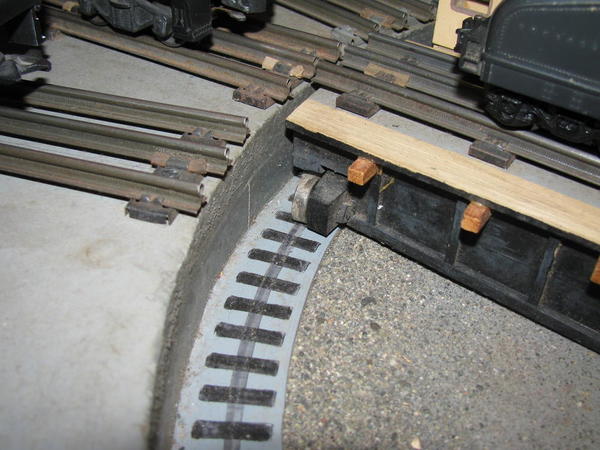
See picture of the TT bridge wheels (note the Sharpie pen ties and rail on the floor of the TT pit ! ) Turntable Detalils 5-29-2016 2016-05-24 005

Wiring of the Turntable and Round House/Spur Tracks

Tracks were added to store trains around the TT being careful of spacing between tracks.  The tracks were wired to a Radio Shack rotary 10 position switch to select the track to be powered.  A momentary contact push button switch (with black push button) was installed on the control panel and wired in series to allow the selected track and turntable bridge track to only be powered when this switch is held down.

The turntable track and all the Round House/stall tracks have common outside rails.  The center rails of the Round House/stall tracks are each wired individually to a spot on the rotary selector switch on the control panel (see Picture below)  thus allowing only one stall track to get power at a time.


Turntable Operation

Once the RH track is selected, pushing down the momentary black push button switch on the control panel allows that track and the TT track are wired for the red lighted LW trans on the right to control the engine to go from the inside loop, over the TT and into that elected stall.

I do not have a diagram.  All of the center rails of the stall and TT track are wired to the black push button switch.  The other terminal of the black push button switch is wired to the output of the Red lighted LW trans.  When the TT track and selected stall track are activated by the momentary switch and power from the Red LW is applied, a light comes on in the little house on the TT to indicate power is on the TT.

The Red lighted Trans always controls the stall tracks, TT track and all of the inside loop on the main board.  It also is wired to all switches on the inside loop of the main board.


Picture Below:

See the RH track selector switch with black pointer knob:   Black push button switch that must be pushed for power to go to selected RH track and turntable is below the black knob on track to TT.  Red and green buttons are for switches and blue are uncoupling track sections.  Black slide switches turn on and off the section of track they are on.  The black slide switches show "white" on and "black" off.  All tracks are blocked and controlled by a slide switch.  All rail switches are always hot or on.
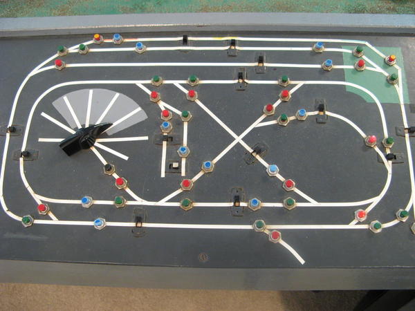
Train Lots 5-10-2016 252

With the selector switches above the red lighted LW transformer can also control the outside loop of the main board as another selection or it can control the outside loop of main board and the new train board thus giving it control of every piece of track on the whole board.


Note on picture below, that one track aligns with the TT and the approach track.  This is the only track that a wrecker caboose and crane car can be sent over the TT and be stored around the TT.  I made sure to leave this track outside of my future Round house to be built and detailed later.

Picture of Track that will allow work caboose and crane car to be stored Turntable Detalils 5-29-2016 2016-05-24 009
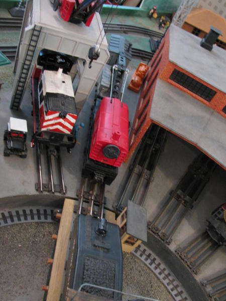

This TT can be detailed to any extent or even scale quality and I detailed my TT for a Toy 027 1950s type of layout.

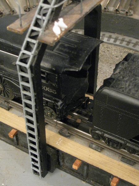
I added details like the lighted TT operator shack, ladders on the bridge to the pit made from cut up N gauge track ties (remove the rails and cut out with every other tie), a TT bridge central tower for overhead wire with ladder, pigeons and poop, and Sharpie penned in rail and ties in the TT pit.

TT bridge has 1/8 inch smooth Masonite deck, grooved with knife to look like wood planks and painted buff to look like wood.  Some sieved coarse sand was glued into the pit bottom.

Picture of Turntable with center mast and ladder, exposed ties, birds, and pit trackTurntable Detalils 5-29-2016 2016-05-24 010
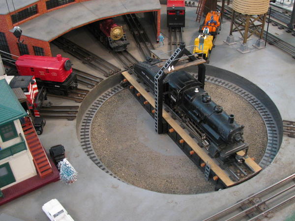

A close up of TT power tower and pigeons, ladders were made from plastic ties from N gauge track with every other tie cut out with X-acto knife or diagonal pliers
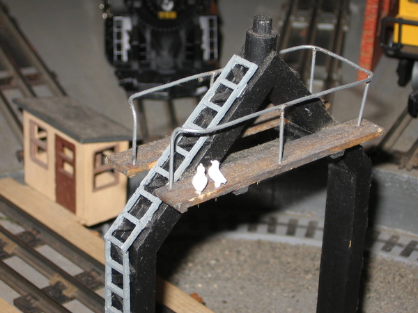
IMG_0306


A TT control cable tower was made from wood and a TT operator shack were made later to add important detail to the TT Bridge.  Also note the wooden support beams for the TT decking and ladders.
IMG_0925


This project takes time, planning and careful measurements to make it all work.  Care must be given to aligning and screwing down the tracks so derailments are few or at least blamed on the TT operator !


To summarize:

A great operating turntable with pit can be built for $10 and using only a hand held jig or saber saw, 1/4 inch electric drill and soldering gun

The turntable can be made for any gauge trains, any size or length of turntable, and located anywhere by automating TT rotation via battery DC junk electric drill or screwdriver motor  :all up to the builder.

The TT really did cost me less than $10 since I had a spare clothes dryer belt.  You could get a belt from a junked clothes dryer, as a used belt is plenty good for this.  Buy a new one for your current dryer and use the old one for the TT !

The turntable uses an inexpensive, easy to find Lazy Susan metal turntable ball bearing unit, to provide smooth and accurate rotation of the turntable.  I used a used clothes dryer belt to provide rotation of the turntable via a hand crank for my turntable.


Remote or Power Operation of this Turn Table

If you do not want to place the TT close to the edge of your layout and be restricted by location due to the length of the clothes dryer belt, one can power the turntable with a used DC electric drill or screw driver motor.  Junked DC electric drills and screw drivers show up often at garage sales and thrifts as it costs a lot to buy new batteries and is often cheaper to buy a new tool.  The drill motor could be powered with a small cheap HO DC transformer in both directions.  This would be easy to power the TT with a shorter belt and pulley on the drill and the the TT could be located anywhere on your layout.

The  TT has worked well since 1977 or almost 44 years and is very reliable.  It would not turn in 2015 and after investigation, the cause was a broken solder joint on one of the grommets on the Vee pulley.  The original was soldered with a 100 watt soldering gun (the only soldering tool I had) and it lasted 38 years.  I re-soldered the Vee with a propane torch, with a soldering iron tip, that gets much hotter.

Post 11 shows how I built a $10 Roundhouse.

Charlie

Charlie,

I am not sure of where I got sidetracked but I just stumbled on your reply with this turntable I want to first apologize and also thank you for the posting of the construction. I will probably print out that post 9 to have it at hand, I'm not sure if I will be around long enough to build it and add to my layout but will keep it just in case.

Again thank you,

Ray

Ray

Thanks for the comments on the TT.  I am glad you liked it and may be the first to make one like it.

With good planning and securing of the Lazy Susan bearing and clothes dryer belt (if you decide to use one or a drill or Elec. screw driver for rotation) before starting, this is a very manageable project.  It probably took me a couple of weeks, with a few evenings and most of one weekend days for each week.  One just has to be careful making measurements and cuts so every thing fits fairly close.  It was enjoyable for me and very pleased on how good it worked and came out.

Extra time was needed to add TT details, the TT bridge and painting with pit gravel but those can be added later.

Charlie

Last edited by Choo Choo Charlie

Post 81      9-28-2022

Repairing Broken Lionel 2025 and 2035 Classification Lights

Lionel 2035 boiler fronts (and others in the family) are notorious for breaking off classification (some call them Marker) lights.  Five of my used 2035 or 2025 engines had missing classification lights when purchased.  At $16 or so, plus $6 to 8 shipping for a new one, this gets out of hand. The picture below shows a Lionel 2065 lighted boiler front (lighted by the head light bulb)  on the left, that was used as a model showing the classification lights inside the diameter of the boiler front.  The broken Lionel 2035 boiler front is shown on the right.


One had one classification light left and I made a marker light out of styrene spurns and runners (the round plastic sticks that hold the parts from the molding process) from plastic model cars or planes.  This will be a very fragile fix, as the classification lights are still sticking out and easy to break off and a picture is below.   IMG_6936


I decided to repair the rest of them by making new classification lights and installing them on the face of the boiler front like the Lionel engines 2065 and 756.  The spurn lenght I used was 5/32 inch in diameter.  I rounded off a square cut end slightly with a file.  I then marked the center of the runner end with a sharp utility knife and use a counter sink drill bit to counter sink a dish for the jewels angled backs.  A utility knife or X-acto can also be used.  I then cut of the end 1/8 inch back to make the marker light with a razor saw in a shoe box lid to keep from losing it.  I  made all ten marker lights and scraped off the paint on the boiler face where it was to be glued.  I used a file to smooth off the rough area where the old classification light broke off.  Epoxy glue was used to glue the classification lights on and to fill any voids where marker light broke off.  They were painted with Krylon satin black paint.  Green jewels were purchased on eBay from seller "trains7272" who advertised brighter original green jewels and they are brighter than most my other jewels.  Jewels were glued in with Pliobond rubber type glue but now I would use E6000 glue.

I know this fix is not like the original and if that is required, buy a replacement.  I am an operator and not into selling my trains so this fix works for me, saving money and still have classification lights that are similar to those of some Lionel engines.


Four Lionel 2035s with glued jewels shown below, 3 have face mounted classification lights that are more rugged than the original.

IMG_6938


A 2035 in the round house showing brightness of jewels.

IMG_6950


Another possible way to replace the broken off classification lights is to make them like the Lionel 2065 boiler front with the lighted classification lights as shown in the first picture, on the left, on the top of this page.  One could drill two 1/16 inch diameter holes in the 2035 boiler front where you want the classification lights.  Then make a classification light frame like above, then drill a 1/16 inch diameter hole in the center before cutting it off the spurns.  Then glue the classification light frames over the 1/16 inch holes in boiler front.  You can add some clear styrene rod in the hole.

An alternate method would be to make the classification light frame from Clear plastic spurns.  Do not drill a hole, then the outside can be painted semi gloss black.

Now you have a lighted classification light.

I hope this helps others revive boiler fronts with broken classification lights and save a few dollars.

Bonus hint:  Here is a way to make replacements for the head light lenses on many Lionel steam locomotives.  Find or buy a section of clear styrene plastic rod, the same diameter of the hole for the head light in the boiler front.  Place a small piece of sheet metal or heavy tin can in a vise to hold it.  Heat the back of scrap of metal with your solder gun or iron until very hot.  Hold the rod of clear styrene plastic rod perpendicular to the piece metal and press it against the heated metal until the rod tip mushrooms out slightly (about 1/32 inch).  Remove and let cool and then cut off the new headlight lenses with a fine tooth hobby or razor saw.  Job done.

Charlie

Attachments

Hide
Images (4)
  • IMG_6930: Broken marker light on right
  • IMG_6936: Repaired marker light
  • IMG_6938
  • IMG_6950
Last edited by Choo Choo Charlie

Jon

Thank you for the kind comment, it has been a fun journey and I am glad you loved the layout.

Here is a photo of Big Steam in the Round House, four 2-6-4, K4s Lionel 2035s, three with modified Boiler fronts.  At first, I usually bought four locos to be able to run 2 trains on 1 track for two loops at the same time.  I did buy four for Lionel 2-4-2s plastic locos, and Lionel 2018s and 2026, 2-6-2s as well.  The stubby Lionel 2035 K4s, with Magna-traction and heavy weight, are still my favorites for my 027 layout but I have been running my Lionel 2065 and 2046 more lately too.

IMG_1922

Charlie

Attachments

Images (1)
  • IMG_1922
Last edited by Choo Choo Charlie

A picture of a Covered Gondola in the May 2020 CTT magazine was found and this was the first time I remember seeing one of them, real or model.  A search found they were common in the 1940s and 50s. Covered gondolas are used to transport items that needed protection from the weather and commonly used by some steel plants to transport steel plate or steel coils.  Other uses are for material that is dusty and that could be dangerous if blown out of an open rail car, like coal ash or radioactive clean up.

The gondola covers in the 1940s and 50s were made like roofs of box cars, with a slightly peaked metal roof and a roof walk grate down the center.  Most covers had hooks on the covers to allow removal with cables with an over the rail crane.  Newer covers for gondolas are made of lighter fiber glass and some are shaped to cover coils of material and could be removed with wheeled Mobile Galion Cranes.

I am always looking for different, unusual cars to add to my layout and train collection and being readily homemade is another plus.  The Covered Gondola is an excellent choice to model as it is uncommon, easy to make from existing gondolas and a junk box car roof and the cover provides another use for my Lionel Gantry Crane.

Lionel makes two sizes of common gondolas, a stubbier, cheaper 8 inch, in at least two levels of detail and a longer, more realistic detailed 9.5 inch in length gondola.  A junk Marx 8 inch box car was used and the roof cut off with a band saw.  It was hard to cut both sides of the roof off the box car evenly (I should have stayed an 1/8 inch off the the line and ground the extra off) and I did a poor job that required some patching to even out the bottom edge.  Probably a razor saw or saw blade in a Dremel should have been used.

IMG_1976


Plastic braces were glued under the cover to hold the cover in the proper place in the gondola car.  The new gondola cover was left the color the existing off white color of the box car roof, as many covered gondola roofs are white.  Four lifting loops were added, to allow removing roof from the gondola, with four cables by my Lionel gantry crane.  I am always looking for different uses or loads for the gantry crane.

IMG_1979

IMG_2056

IMG_2033

IMG_2008

I am planning to make a lifting rig from four pieces of black braided fishing line and four hooks from thin solid wire.  The gantry crane hook can be used.  Another method is to glued the four lines to the a steel washer with E6000 glue.  Then the magnet of the Lionel Gantry Crane can be used to pick up or lower the  steel washer rig, with the cover attached. The cover can then be removed or installed on top of any 8 inch gondola rail car.

IMG_2043

Only one 8 inch gondola cover for my smaller gondola cars will be made as it can be installed on any one of my small gondola cars.  Another gondola cover, for my 9.5 inch gondolas rail cars, may be made when a junk 9.5 inch box car is found at a train show.

Charlie

Attachments

Hide
Images (6)
  • IMG_1976
  • IMG_1979
  • IMG_2056
  • IMG_2043
  • IMG_2033
  • IMG_2008
Last edited by Choo Choo Charlie

John

Thanks for the kind comments.  I often post projects on other topics and re-post them here to have items for my layout in one place.  There is a Table of Contents at the bottom of page 1, post 1 of this topic that tells page number and the number of the post next to the post description.  You will find you have seen many or most of the posts on this topic before.

Have a very Merry Christmas and Happy Holidays.

Charlie

Last edited by Choo Choo Charlie

Post 83          4-18-2023           Updated 5-10-2024

Gondola Cars on the Layout

Recently gondola cars have my attention.  The prior post showed the covered gondola I made up. That got me into fixing up several Lionel 9.5 inch gondola bodies I had for years with trucks so I could run them.  Gondolas are flat cars with sides and ends and box cars are gondolas with roofs.

I usually have on gondola for use with the Lionel 12834 Operating Gantry Crane loading and unloading canisters that have a metal washer to allow picking up with a magnet on the crane.

IMG_2337


I always have that gondola or another one in the operating car train (seen at top of picture below) that stays on the siding below the double dog bone on the new train board.  That car has most of layout operating cars so it can go around to the cattle pen, milk car platform, icing station and other operating accessories.

The bottom of the picture shows a Lionel 9.5 inch gondola on the left and a 8 inch gondola on the right.

IMG_2352


Recently I made a short 8 inch Lionel gondola into a tank car by installing the tank from a Lionel tank car into the gondola, showing the versatility of gondola cars.

IMG_2350


Here is my Post War Lionel Erie 3444 Animated Cop and Robber Gondola operating car with the original vibrator motor, sound and all.  Also, a free look at the Lionel 9908 Traveling  Aquarium car noisily operating too.

Lionel 3444 Cop & Robber Gondola 2024-05-10 004


Gondola cars can be pressed into moving automobiles in an emergency.

IMG_2356


Gondola cars are also used to haul loads like coils of rolled steel, often with covers to protect the coils from weather.

IMG_2346


Gondola can haul electrical cables or cable empty reels

IMG_2355


Gondolas can haul gravel or track ballast (ignore derailment !)

IMG_2344


Gondolas could haul NASA Mercury capsules if necessary

IMG_2357


Gondolas can transport Christmas Candy to Kids

IMG_2358


Gondolas can haul logs

IMG_2360


Gondolas can haul horses

IMG_2359


Gondolas can haul drums

IMG_2361


Gondolas can transport Oscar Myers Wiener cars

IMG_2363

Charlie

Attachments

Images (14)
  • IMG_2337
  • IMG_2352
  • IMG_2350
  • IMG_2356
  • IMG_2346
  • IMG_2355
  • IMG_2344
  • IMG_2357
  • IMG_2358
  • IMG_2360
  • IMG_2363
  • IMG_2359
  • IMG_2361
  • Lionel 3444 Cop & Robber Gondola 2024-05-10 004
Videos (1)
Lionel 3444 Cop & Robber Gondola 2024-05-10 001
Last edited by Choo Choo Charlie

Post 84     6-7-2023

Revised 7-2-2023

Homemade Borden's Butterdish Milk Tank Car

I have recently learned about Borden’s Butterdish Milk Tank Cars and their use, and that Lionel 6-19479, 6-19445, 8 inch long cars and American Flyer 412 were made in the past as well as numerous models in HO and N scale.  These cars can be googled to see what they look like.  The real Borden’s Milk Tank Cars have a unique Art Deco design and look very modern and unique, especially some of first ones with extra fins on the top.  The Art deco top fins were removed during WW2 as the metal was needed for the war effort some report.  This little project turned into a learning experience and had more little stumbling blocks than I expected.

Picture of my Homemade Borden’s Milk Tank Car, BFIX 520

IMG_2479

Pictures of the last remaining Borden’s Butterdish Milk Tank Car can be seen at link below.  This is the one I modeled.

https://en.wikipedia.org/wiki/...s_Railway_Museum.JPG


The link below shows how the original Butterdish Borden’s Milk Tank Cars were made with more Art Deco fins on the top of the car.  These fins were a decoration and were dropped after the first or second car.  I may add those top fins later as they are really neat.  A couple of Popsicle sticks could be used.

https://www.walthers.com/quot-...less-wheels-couplers.


Link below shows how a wooden mold was used to make plastic sheet body and drawing of original Borden Milk Car with Art Deco on top

http://dandhcoloniemain.blogsp...dish-car-part-1.html


The link below shows so history of the Butterdish cars in Part two and some good pictures of BFIX 520

http://nyow.org/Articles/Butterdish/butterdish.html


The link below shows a Large number of images of Borden's  Milk Cars, with some showing Lionels and Am Flyer Borden's Milk Cars.

https://www.google.com/search?...biw=1071&bih=482


The Borden company had 35 or so Milk Tank Cars made in the late 1930s to transport whole milk from small rural train stations to the creamery.  The Borden’s Company press release of February of 1936 noted, the ‘Butterdish Car’ is “the first all-metal, stream-line milk tank railroad car ever built”.   Dairy farmers must milk each cow daily and transport the milk with tank trucks or hauled it in 10 gallon cans to the train depot each day in the Northern Midwest and Northeastern states.  Fresh whole milk can last 24 hours if kept cool.  Borden’s cars had two 3000 gallon glass lined tanks mounted on a flat car.  The cars were designed in an Art Deco style popular at that time.  The tanks had a insulated tanks or insulation under the frame which was made to surround the tanks and the cars were not refrigerated.  These cars were picked up daily and transported to nearby creameries.  Only one Borden’s Milk Tank Car, the BFIX 520, still exists and it has been restored and is in the Illinois Railway Museum in Union, Illinois.

I had all the materials to build the tank car on hand except the music wire for the handrails.  Much time was taken to decide on the measurements of the car.  A small cheap, 8 ¼ inch long X 2 1/8 wide flat car with trucks was chosen.  Side pieces of plastic were added to the bottom of the flat car deck to reinforce it to take the weight of two 3000 gal tanks.  I thought Lionel’s Borden’s Milk Tank Car tank body was either too high or too short making it look too fat compared to pictures of the real car.  I found a strong cardboard mailing tube that was 1-11/16 inches in diameter and at least 9 inches long, to use for the car tank body.  The 8 ¼ inch car I chose is 33 ft long for the real 40 foot long car or 82.5% of the real car.  This is close to 027 Toy trains cars percent of O scale at ¼ inch to the foot.  If I had used as standard Lionel flat car that is 10 inches long it would have been 40 ft real car length or O scale at ¼ per one foot.

I found two write-ups on making an HO Borden’s Milk Tank car that were made by making a solid wooden mold of the car body and heating a thin sheet of smooth Styrene plastic over the mold to make the body.  Since I had a good cardboard tube, it was decided to make the body by steaming a piece of 1/16 inch thick medium hardness balsa wood over the tube.  Some 60 year old Medium hard balsa wood seemed to be both somewhat hard and yet flexible enough to bend without breaking or splitting.

I made a base out of 1/8 inch Masonite, the same width as the tube I then glued the tube to the base. This total width, including 1/8 inch for the balsa wood,  would leave ¼ on each side of the tube body when put on the flat car base which was necessary room for personnel to walk on the sides of the car.  The balsa was glued to the top of the tube with two sheets being used.  The balsa was slowly bent around the tube, with a gloved hand and a clothing steam iron supplying the steam, and the balsa was pinned in place.  When cooled and dry, the balsa was glued the tube and to the base, with Elmer's glue and pinned until the glue dried.

IMG_4170


The pieces of Popsicle sticks were glued inside the cardboard tube and behind the balsa wood on the sides between the base and the tube with Elmer's glue to strengthen them both.  Some wood blocks were glued in the bottom ends inside the tube to allow screws to be used to hold the tank body to the flat car.

When all was dry, the ends of the tube tank body were cut off at an angle of the real car, 15 degrees, with a band saw giving the neat, angled end of this unique car. The total length was made to give a 1 scale foot or ¼ inch of walkway at the end of the car and is 7 3/8 inched long.  Then, the tank body was placed on the car flat car body.  Observations showed the car tank was too high and the car looked too fat, versus the real car.  So much for for all that planning to make a slimmer car than the Lionel fat boy.

IMG_2451


It was decided to cut 3/8 inches off the bottom of the tank with the band saw, a 2 minute job.  This looked much better, and part of the cardboard tube was cut off too, which was not a problem.  So much for all that planning with rulers and pencils.

Picture of car with the 3/8 inch removed- looks slimmer and closer to the real car

IMG_2454

This picture shows the car with the 3/8 inch cut off piece re-inserted to where it was cut from, on the bottom where it came from, for comparisons sake.

IMG_2453

Wood filler was used to smooth out the balsa wood and fill in the seam on the top. Pieces of 1/8 inch balsa wood were added to the ends of the car.  A small 1/8 inch piece of balsa was added on the end of the tank to be the hand brake housing to allow a brake wheel to shorten a chain that would apply the wheel brakes.  Two Art Deco tank end fins were hand sketched and transferred to Popsicle sticks and glued to the ends of the tank car body to be the art decor touch and hold the ends of the wire handrails.

A few pieces of plastic stripping were added to the tank side to be the two door outlines.  The doors are used to get access to the valves and hose connections to load and unload milk.  Holes for the handrail stanchions were located and drilled.  Twelve small cotter keys, with diamond shaped loops, were bent to circles and painted medium gray.  Holes were drilled in the flat car to attach the tank and a hole was drilled for the brake chain.

IMG_4180

There was concern that the balsa would be too soft to use the rub on letters & numbers I had in place of decals.  I considered making decals, as I have an HP laser jet printer that uses black toner that could make black letter decals.  Further reading lead to an article that laser printers, that use black toner, will yield black letters that will turn brown in time, so I was stuck with rub on letters.  I made up a couple of batches of five minute epoxy, to finger on the balsa, on the tank car balsa top and sides to harden it up more.

The flat car was painted medium blue, and the tank was painted with several coats of glossy white, with Rustoleum being better than cheap Walmart paint I tried first.  Walmart paint had problems covering the old Green Squadron wood filler I used some places.

The rub on letters and numbers were applied, very gently.  It was found easier, quicker, and  more accurate, to leave all the numbers and letters on the 8.5 x 11 inch sheet than to cut it up into small strips.  The numbers and letters were sprayed with glossy clear paint as each sides letters were finished, to keep from messing up the letters when handling to do the next side.  Glossy clear paint was also applied to the flat car as the blue paint used had a flat sheen.

Music wire was bent to be the hand railings. Two small brass tubes were made to join the two handrails at each end of the car.  The stanchions and tubes were not glued in and remain in place quit well without glue.  A brake chain was made from 2 inches of coarse cotton thread and knots were tied close to each other, to be the links and the chain was painted silver.  The hand brake wheel is from an old Lionel boxcar.  I painted it light gray as well as the stanchions as that allowed them to show up but not as much as black.  The handrail was left natural steel (painted with clear) as I did not want have them show up as much as the black handrails in some of the pictures of the real car.

IMG_2473

IMG_2480

IMG_2472

The Butterdish (the correct name should be Butterdish Cover) Milk Tank Cars are rarer than some cars especially the Lionel 3664 Automatic Operating Milk car, which is properly the most popular operating car Lionel ever made and the favorite of all the young layout visitors.

6-17-2023 UPDATE

The original Butterdish cars were made with Art Deco metal top fins that were removed during WW2 ,to get the metal for the war effort.  These top fins make the Butterdish car more Art Deco-ish and unique.


A few pictures of the real car and many of models made of the original Borden's Milk Tank Car seem to show two types of top fins.  Therefore, two sets of Art deco TOP Fins were made from two Popsicle sticks glued together, end to end for each set, one Higher and one Lower.  They were hand sketched on paper and transferred.  They were sawed out on a 50 year old, recently restored Delta 24 inch jig/scroll saw (that is in the garage with the dirty power tools), saws much more accurately than my old 18" Craftsman saw I use in my shop.

IMG_2533

IMG_2535

The fins are put on the car with thin two sided tape.  For now, I will vary the top fins as none, High or Low but the Low sized top fins are my favorite for now .

Higher Fins

Borden Hi Fin 6-17-2023 2023-06-17 002

Lower

Borden Low Fin 6-16-2023 2023-06-16 001

IMG_2541

Charlie


.

Attachments

Images (14)
  • IMG_2479
  • IMG_4180
  • IMG_4170
  • IMG_2451
  • IMG_2453
  • IMG_2454
  • IMG_2473
  • IMG_2480
  • IMG_2472
  • Borden Hi Fin 6-17-2023 2023-06-17 002
  • Borden Low Fin 6-16-2023 2023-06-16 001
  • IMG_2533
  • IMG_2535
  • IMG_2541
Last edited by Choo Choo Charlie

6-17-2023  Up Date to Post 84 with Art Deco Top Fins added.

Additional photos and descriptions have been added to the original Post 84, and the below is a summary.

The original Butterdish cars were made with Art Deco metal top fins that were removed during WW2 to get the metal.  These top fins made the car more Art Deco-ish and unique.


Two sets of TOP Fins were made, one Higher and one Lower.  The fins are put on with thin two sided tape.  For now I will vary the top fins as none, High or Low but the Low top fins are my favorite for now .


Higher Top Fins

Borden Hi Fin 6-17-2023 2023-06-17 002


Lower Top Fins    My current favorite.

Borden Low Fin 6-16-2023 2023-06-16 001

Charlie

Last edited by Choo Choo Charlie

Post 85          7-10-2023

Scratch Building a Sawdust Burner for sawdust from Lionel 464 Saw Mill

I found a used Glade room deodorizer container and wondered what I could make from it.  It had a sort of Art Deco shape and was about 5 inches high and 3 inches in diameter.

IMG_2579

Searching around lead me to making a Sawdust burner to be adjacent to my Lionel 464 Saw Mill.   I had not known of Sawdust burners prior.


History:  Sawdust burners were used to dispose of waste saw dust produce from sawing logs into lumber at smaller sawmills located in the Oregon, northwest, western Canada and across the southern states.  Most were adjacent to small sawmills.  Large sawmills, like the restored at the Southern Forest Heritage Museum in Long Leaf, Louisiana had their own electrical power houses that burned wood and sawdust waste.  Several years ago, we visited this restored sawmill located about 100 miles northwest of Baton Rouge and it had its own small Railroad also.

https://forestheritagemuseum.org/long-leaf-mill

Looking at images showed many sawdust burners, mostly old pictures and pictures of the few burners that survived.  The 1930’s and 1940’s were the heyday for sawdust burners.  Sawdust burners were all phased out due to pollution and now sawdust is used to make particleboard, cat litter and is being added to food.  Yes food, and Kraft Grate (powered) Parmesan Cheese lists cellulose fiber (sawdust) as an additive.

There are numerous model railroad models of Sawdust burners (also called Teepee and Beehive burners) sold, some kits and some made by 3D printing.  These can be found on eBay.


I realized the Glade container would be too small and adding more height to its plastic body would be difficult.  Sawdust burners come in many sizes but most are about 40 ft high which would be 10 inches in O scale and too high and big for my small location next to the Lionel 464 Saw Mill.  I decided that the sawdust burner needed to be taller than the roof of the Saw Mill so that the smoke and some times flames would not burn down the Saw Mill!  I settled on 6 inches minimum high and about 4 inches in diameter.  I decided to make the burner cone body out of construction paper.  It is difficult to make a perfect cone out of construction paper or anything else.  I made a paper pattern that seemed to make a cone and copied it on construction paper and cut it out.  I made two as that would make the cone stronger when glued together.

IMG_2570


Cones two layers being glued together

IMG_2571

The cone was reinforced with two rings of thin plywood, on the bottom and in the middle.  Another ring donut was made for the top, having a recess to allow installation of the wire screen spark suppressor on top of the burner to catch sparks.

IMG_2577

IMG_2574

Top ring with recess for wire screen

IMG_2573


The wire screen spark suppressor was made from a small piece of aluminum window screen wire which was formed over a piece of 1 ½ inch diameter PVC pipe with rubber bands.  The area of contact of the screen wire and rubber bands were coated with Elmer’s white glue and allowed to dry.  The rubber bands were removed and dome shaped screen wire was removed from the PVC pipe and installed on the top at the recessed part of the donut ring and glued on with Elmer’s glue.  It was later filled in with wood filler and partly painted flat black.

IMG_2766


The base of the real Burners were poured concrete on the ground.  Most sawdust burners had vertical steel frames made into a teepee shape and had horizontal circular frame sections added.  Sheet metal was added between the horizontal and vertical section to fill out the teepee shape and strengthen the structure.  I doubt the real teepee was welded and probably was bolted together.

Horizontal rings were added to the cone and were made from some medium diameter cotton string.  The string was glued on the cone with Elmer’s white glue.

IMG_2674

Then some pieces of model double wooden beading, each about 1/32 inch diameter were separated, cut to size and glued on to make the vertical sections.  Note:  the rubber bands holding on the vertical pieces and at the bottom and there is the outline for a bottom side door.  The door will allow the burnt ash to be removed from the real Teepee.

IMG_2697


I have seen pictures of newer sawdust burners that appear to be silver or metal in color.  After a short time of being used, the outside of the Teepee becomes rusted as the burner was probably not used all the time.  I decided to make mine more realistic and spay painted it with a rust colored primer.  The painting of the burner became rather weathered looking as it was not possible to make it smooth, being paper and have numerous small sections making sanding and sooth prime painting impossible.

IMG_2716


Sawdust can be transported from the Saw Mill to the Sawdust Burner is several ways,  A conveyor belt or screw can be used as well as a pneumatic pipe is another way.  The pneumatic pipe has to have a strong blower and as cyclone to separate the air from the sawdust at the burner to work.

I chose a more common and simpler conveyor belt to transport the sawdust from the Saw Mill to the Sawdust Burner.  The conveyor is covered to keep the saw dust from blowing off the belt and dry from rain.  The conveyor was made from balsa wood.  It has grooves showing the top covers are removable in smaller sections.  The bottom shows the black rubber belt and silver return rollers.  The Conveyor is labelled "MAC" Equipment Co., a conveyor brand I am familiar with.

IMG_2757


I wanted to install a red light near the top of the burner stack to simulate the burning of the sawdust.  I did not add a means of smoke making as my wife has outlawed all smoke making with my model railroading as she has a very sensitive sense of smell.  I used parts from mini Christmas tree lights, providing the pigtails and socket and holder for a red, 12v mini light.  I have used mini Christmas tree lights and pig tails for most of the lights in on my layout, for buildings, floods lights and other lights.  I made holder for the light bubble socket and bulb from an old clear red ball point pen and installed two fat ice cream wooden stick across the inside diameter of the cone, to hold the light holder and the wires.  This system allows the bulb to move about 1 ½ inches vertically, to change the bulbs position at the top near the wire screen spark restricter and change the light intensity.  An aluminum foil disc has been placed below the bulb to direct the light up.


Picture below shows the circular clear red old ball point pen body glued to the wide ice cream stick and the red, 12v, mini Christmas tree light bulb

Burner 7-10-2023 2023-07-10 005


A square hole was cut in the side of the Sawdust Burner to allow installation of the sawdust conveyor that comes from the Saw Mill

IMG_2768


The stack light is the only way to give this mundane sawdust burner some life and action.   I have tried various light bulb positions and inside paper rings color changes.  Most positions hid the light bulb from sight which is good.  I am still experimenting with different positions and paper rings about the top piece to get the best effect for the stack light both day and night operation.  I even made one paper ring with flames.  Most of the time the real sawdust burners do not show a flame discharging from the top.  I have seen one internet picture showing a rush of fire out the top but that would be dangerous and put the forest and saw mill at risk.  Some saw mill burners have electrically driven fans at the base of the burner, supplying extra air but that is not common.


Pictures of installed Sawdust Burner next to the Lionel 464 Saw Mill

IMG_2737


View of covered MAC conveyor belt in use and a fire in the Burner

IMG_2735

IMG_2745


Updated picture of Sawdust Burner stack glow using a piece of shinny red card board

Believe this a the winner at least in the picture department.  Notice the Lionel UP 9203 MPC Log Dump cars that can dump onto the Sawmill log deck and receive logs from the Lionel 6-12774 Automated Log Loader at the maintain on 027 track.  Some log dumping cars require the height of regular O gauge track to dump on the 464 Saw Mill log deck. 

DSCN0025


Below door, on left, in bottom of Burner, with hinges and fasteners to keep it closed in dark gray and the Bulldozer used to remove ash

IMG_2758


I think the Sawdust Burner turned out very well and it was challenging to build such a simple item.  The train layouts log and lumber operation is the most complete operation on the layout.  Logs can be loaded from the mountain forest operation log loader, into log dumping cars.  These cars can be railroaded from the mountain to the Lionel 464 Saw Mill and dumped onto the Saw Mill.  The logs are then sawed into lumber and discharged from the 464 Saw Mill.  Waste saw dust is burned in the saw dust burner.

Charlie

Attachments

Images (19)
  • IMG_2579
  • IMG_2570
  • IMG_2571
  • IMG_2577
  • IMG_2574
  • IMG_2573
  • IMG_2674
  • IMG_2697
  • IMG_2716
  • IMG_2757
  • IMG_2766
  • IMG_2768
  • IMG_2737
  • IMG_2735
  • IMG_2745
  • IMG_2758
  • IMG_2731
  • Burner 7-10-2023 2023-07-10 005
  • DSCN0025
Last edited by Choo Choo Charlie

Add Reply

Post
×
×
×
×
Link copied to your clipboard.
×
×