Thanks for the clarifications. I assumed that under a prior owner the factory wiring may have been changed up. For a novice like me, this just added to the confusion. However, and with your support, I do have a better understanding of how these motors run.
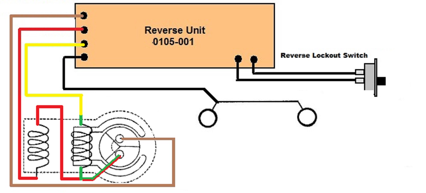
The voltage readings I got from the board leads follow: brown @ 12v (same as transformer setting) when meter grounding lead to frame) and @ 1v when meter grounding lead connected to red and yellow board wires (regardless of the lockout switch setting). So, I assumed the grounding directional circuits were faulty (open). Given your clarification I'm at loss to explain the current wiring scheme's results.
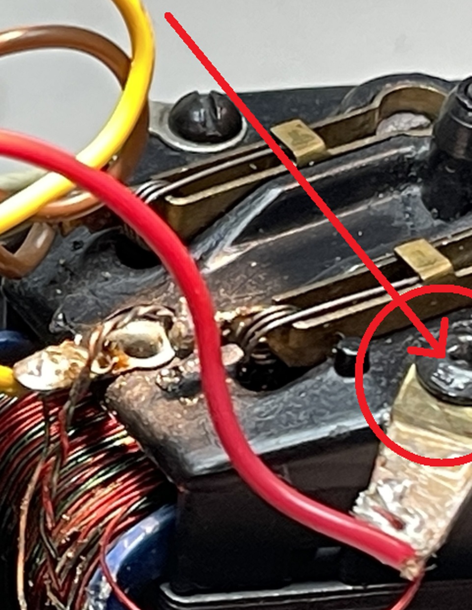
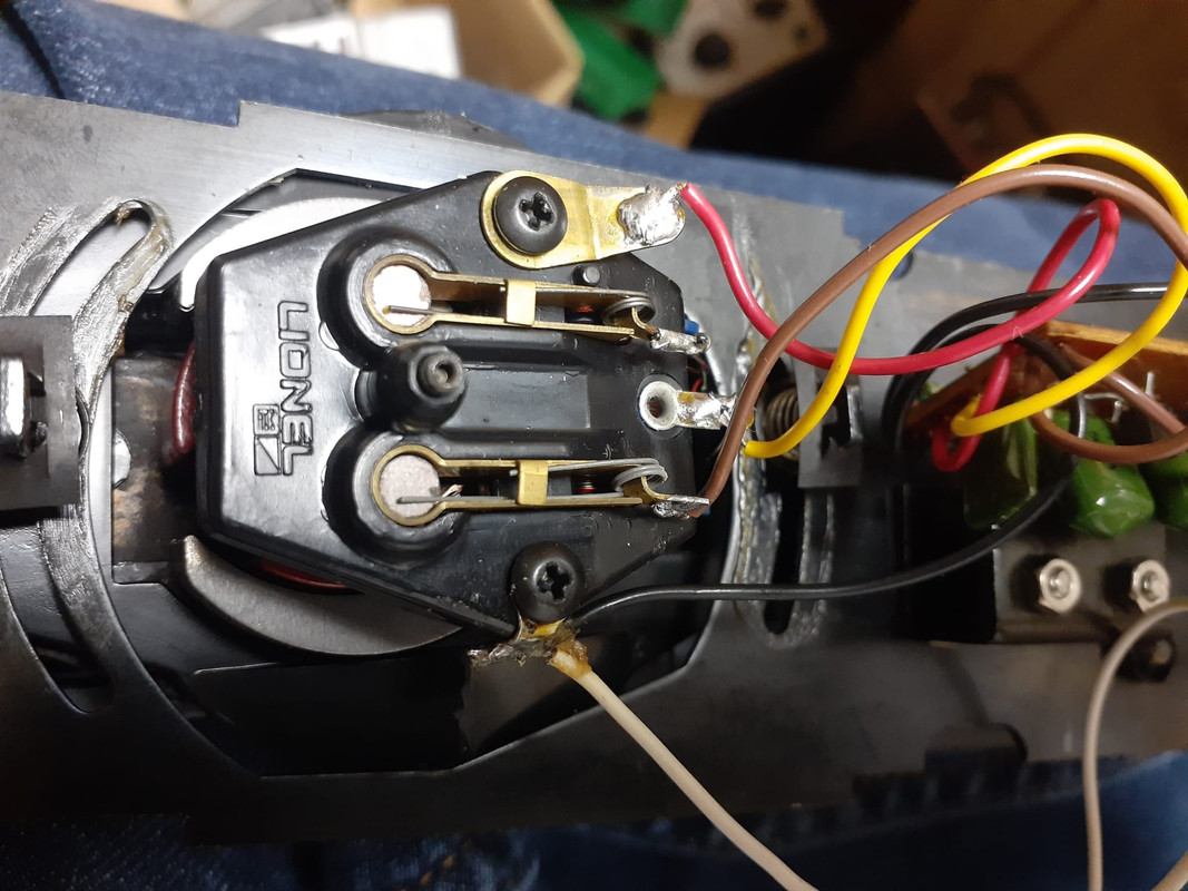
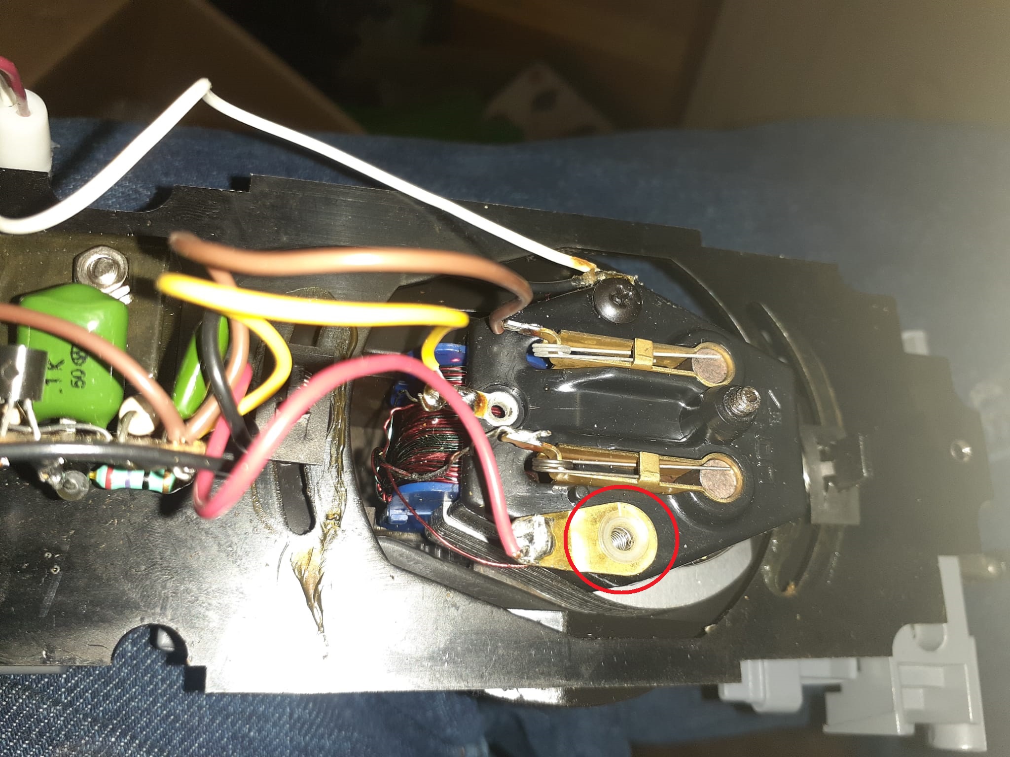
Currently, and I thought in acceptable for the time being, running condition, the brown wire is soldered to one brush holder and a set of green/red winding leads are soldered to the other brush holder. The red and yellow from the board are capped and tucked away (doing nothing). The other red from the winding is grounded on the brush plate screw. The other green from the winding remained untouched on the lug between the brush holders.


